 |
|||
|
|
|||
|
|
|||
| ||||||||||
|
|
 TM 9-2320-363-20-2
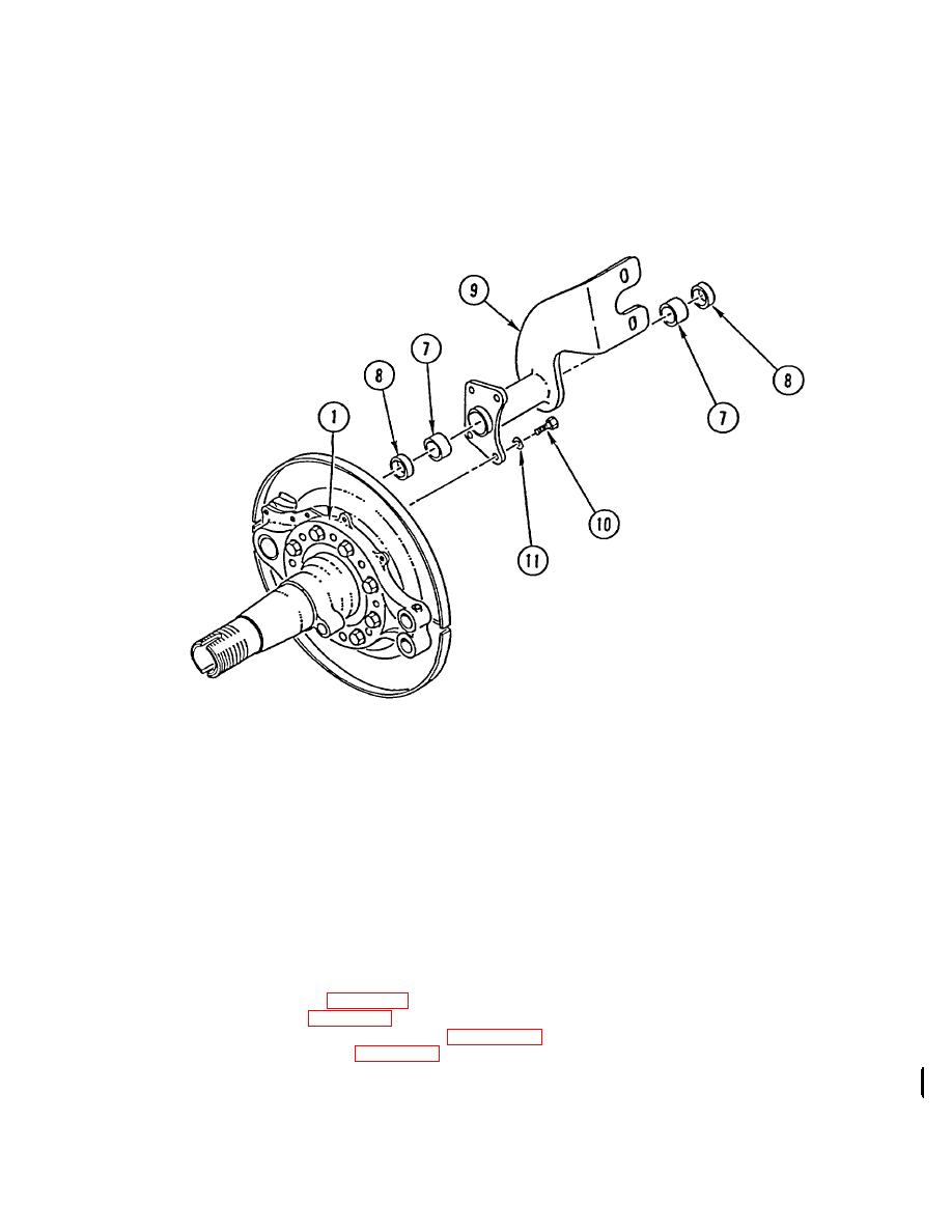
NOTE
Position spider as matchmarked during removal.
1.
INSTALL SPIDER (1), EIGHT WASHERS (2), EIGHT FLANGE BOLTS (3), EIGHT WASHERS (4), AND EIGHT
NEW LOCK NUTS (5) ON AXLE FLANGE (6). TIGHTEN LOCK NUTS TO 150-175 LB-FT (203.4-237.3 N.m) IN
SEQUENCE SHOWN.
2.
APPLY LIGHT COAT OF GAA TO TWO BUSHINGS (7) AND TWO GREASE SEALS (8).
NOTE
Install bushings with label ends facing each other. Install to depth of 3/8 in.
from each end.
Install each grease seal with lip facing toward slack adjuster.
3.
INSTALL TWO BUSHINGS (7) AND TWO GREASE SEALS (8) ON SPIDER (1).
4.
INSTALL BRAKE CHAMBER BRACKET (9), FOUR CAPSCREWS (10), AND FOUR WASHERS (11) ON SPIDER
(1).
NOTE
Follow-on Maintenance:
Install rear brakeshoe and lining (page 4-413).
Install rear air brake chamber (page 4-424).
Install rear Anti-Lock Brake System (ABS) sensor (page 4-290.2).
Install rear slack adjuster and S-cam (page 4-437).
Lubricate brake chamber bracket (Unit PMCS, TM 9-2320-363-20-1).
Change 3 4-433
|
|
Privacy Statement - Press Release - Copyright Information. - Contact Us |
