|
| |
TM 5-2420-222-34
14-3.
HYDRAULIC PUMP ASSEMBLY MAINTENANCE (Con’t).
5.
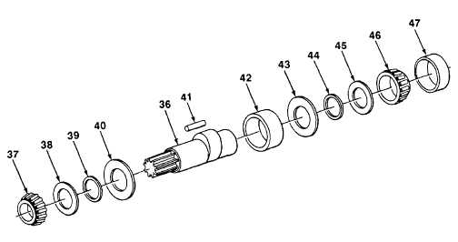
Install bearing washers (43 and 44) and washer (45) on shaft (36).
6.
Using installer and arbor press, install cone and rollers (46) until seated on shaft (36).
7.
Position outer bearing ring (42) over shaft (36). Coat 25 roller bearings (41) with hydraulic fluid, and insert roller
bearings between outer bearing ring and shaft.
8.
Install bearing washer (40), bearing washer (39), and washer (38) on shaft (36).
9.
Using installer and arbor press, Install cone and rollers (37) until seated on shaft (36).
10.
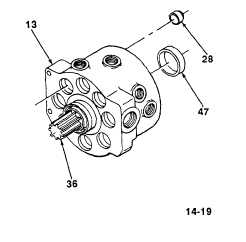
Install shaft (36) in hydraulic pump housing (13).
11.
Install bearing cup (47) in hydraulic pump housing (13).
CAUTION
Ensure that no more than 850 lb (386 kg) of pressure are
used when Installing valve seats. Equipment may be
damaged.
12.
If removed, install eight valve seats (28) in hydraulic pump housing (13)
using arbor press.
13.
Using depth micrometer gage, measure distance from surface of
hydraulic pump housing (13) to shoulder of valve seats (28). Distance
must be at least 0.870 in. (22.098 mm).
TA701554
14-19
|