 |
|||
|
|
|||
|
|
|||
| ||||||||||
|
|
 TM 5-2410-237-23
RIPPER ASSEMBLY MAINTENANCE - CONTINUED
0238 00
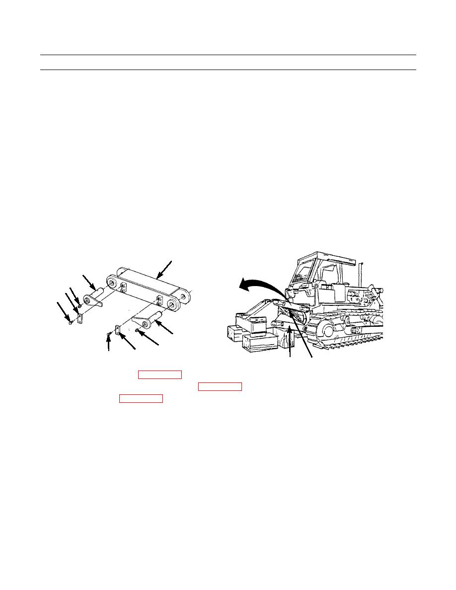
INSTALLATION - CONTINUED
CAUTION
Be careful not to damage cylinder or valve hoses and fittings while installing pin assemblies.
Ensure markings of sides, front, rear, up and down are facing correctly before installation of connect-
ing link.
17.
Attach a nylon sling and a suitable lifting device to connecting link (5).
18.
Place a bar between lift cylinder (6) and frame assembly (2), to prevent damage and movement of lift cylinder during
installation of two pin assemblies (7).
19.
Position connecting link (5).
20.
Install two pin assemblies (7) through connecting link (5).
21.
If removed, install grease fitting (8) to each end of pin assembly (7).
22.
Install plate (4) at each end of connecting link (5) with two bolts (3).
23.
Repeat steps 17-22 for connecting link (5) on other side of ripper.
5
7
8
4
3
7
8
4
3
387-762
2
6
24.
Install ripper control valve (WP 0206 00).
25.
Fill hydraulic tank and bleed system as needed (WP 0225 00).
26.
Install ripper shanks (WP 0240 00).
27.
Apply GAA grease to 20 ripper assembly grease fittings (TM 5-2410-237-10).
28.
Check ripper for proper operation (TM 5-2410-237-10).
END OF WORK PACKAGE
0238 00-8
|
|
Privacy Statement - Press Release - Copyright Information. - Contact Us |
