 |
|||
|
|
|||
|
|
|||
| ||||||||||
|
|
 TM 5-2410-237-23
RIPPER ASSEMBLY MAINTENANCE - CONTINUED
0238 00
REMOVAL
NOTE
Beam weighs 2,000 lb (908 kg).
Frame assembly weighs 990 lb (449 kg).
Connecting links weighs 227 lb (126 kg).
Ripper lift cylinder weighs 195 lb (89 kg).
1.
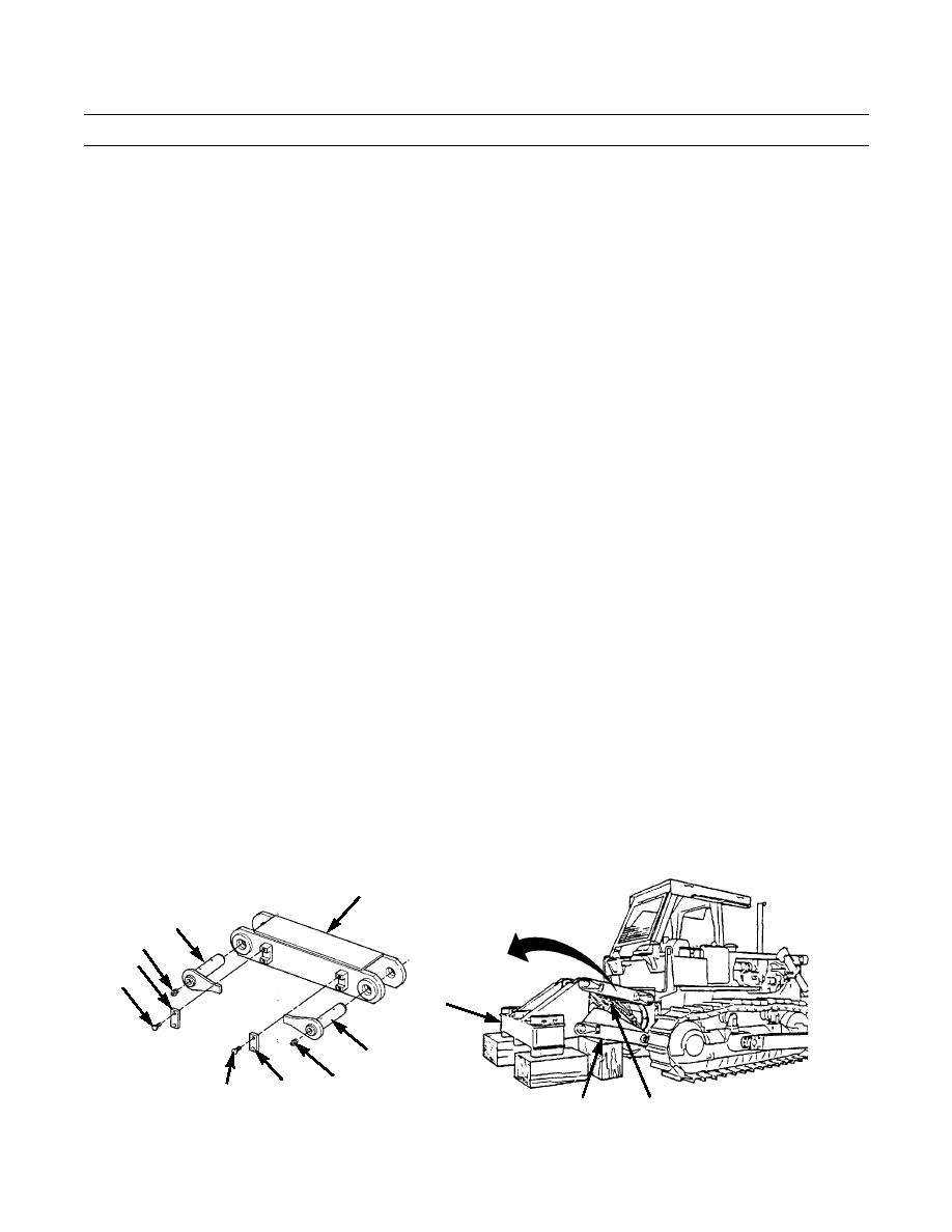
Place cribbing underneath beam (1) and frame assembly (2).
2.
Cut locking wire and remove four bolts (3) and two plates (4) from connecting link (5).
3.
Attach a nylon sling and a suitable lifting device to connecting link (5).
4.
Place a bar between lift cylinder (6) and frame assembly (2), to prevent damage and movement of lift cylinder during
removal of two pin assemblies (7).
CAUTION
Be careful not to damage lift cylinder or valve hoses and fittings while removing pin assemblies.
NOTE
Mark all pin assemblies for installation.
Mark connecting link to indicate sides, front, rear, up and down.
5.
Remove two pin assemblies (7) from connecting link (5).
6.
Remove grease fitting (8) from end of each pin assembly (7), if required.
7.
Lift and remove connecting link (5) from machine. Remove nylon sling and lifting device from connecting link.
8.
Repeat steps 2-7 for connecting link (5) on other side of ripper.
5
7
8
4
3
1
7
8
4
3
387-762
6
2
0238 00-2
|
|
Privacy Statement - Press Release - Copyright Information. - Contact Us |
