 |
|||
|
|
|||
|
|
|||
| ||||||||||
|
|
 TM 5-2410-237-23
BEVEL GEAR AND SHAFT REPLACEMENT - CONTINUED
0127 00
INSTALLATION - CONTINUED
b.
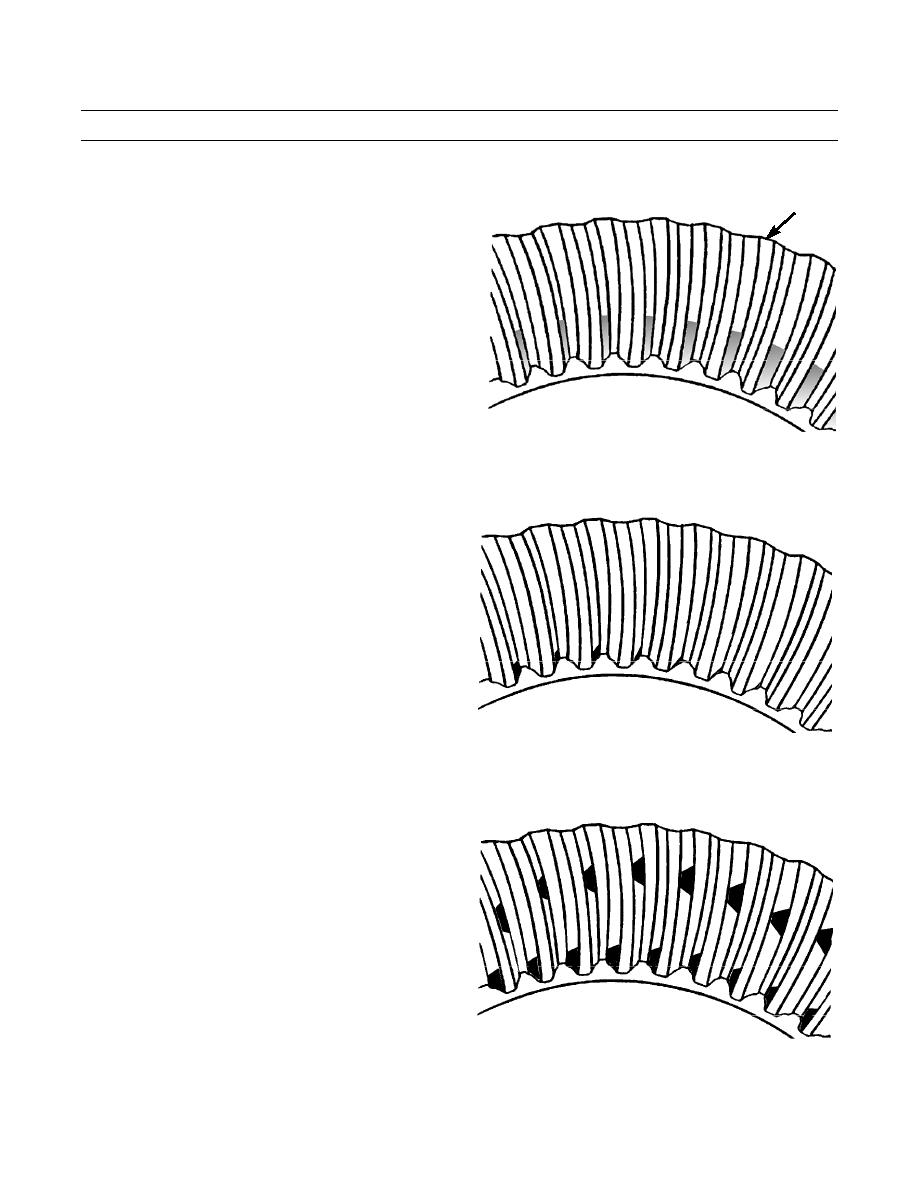
With no load, correct tooth setting will be as
16
shown. The area of contact starts near toe of gear
and goes 30% up length of tooth. With this set-
ting, when load is put on gear it will be over cor-
rect area of teeth.
387-455
c.
If bevel pinion shaft is too far away from bevel
gear, short toe contact will be the result as
shown. The teeth of bevel pinion shaft will be in
contact with toe ends of convex faces (part that
makes a curve toward outside), and top edge of
heel end of concave faces (part that makes a
curve toward inside). To correct this, add shims
between bevel pinion shaft and bearing cage of
transmission. Check gear clearance (backlash)
and tooth contact again.
SHORT TOE CONTACT
387-456
d.
If bevel pinion shaft is too near to center of bevel
gear, short heel contact will be the result as
shown. The teeth of bevel pinion shaft will be in
contact with toe ends of concave faces (part that
makes a curve towards the inside) and the heel
ends of convex faces (part that makes a curve
toward the outside). To correct this, move pinion
shaft away from bevel gear by removal of shims
between bearing cage of transmission and bevel
pinion shaft. After doing this, check gear clear-
ance (backlash) and tooth contact again.
SHORT HEEL CONTACT
387-457
0127 00-10
|
|
Privacy Statement - Press Release - Copyright Information. - Contact Us |
