 |
|||
|
|
|||
|
|
|||
| ||||||||||
|
|
 TM 5-2410-237-23
BEVEL GEAR AND SHAFT REPLACEMENT - CONTINUED
0127 00
INSTALLATION - CONTINUED
6.
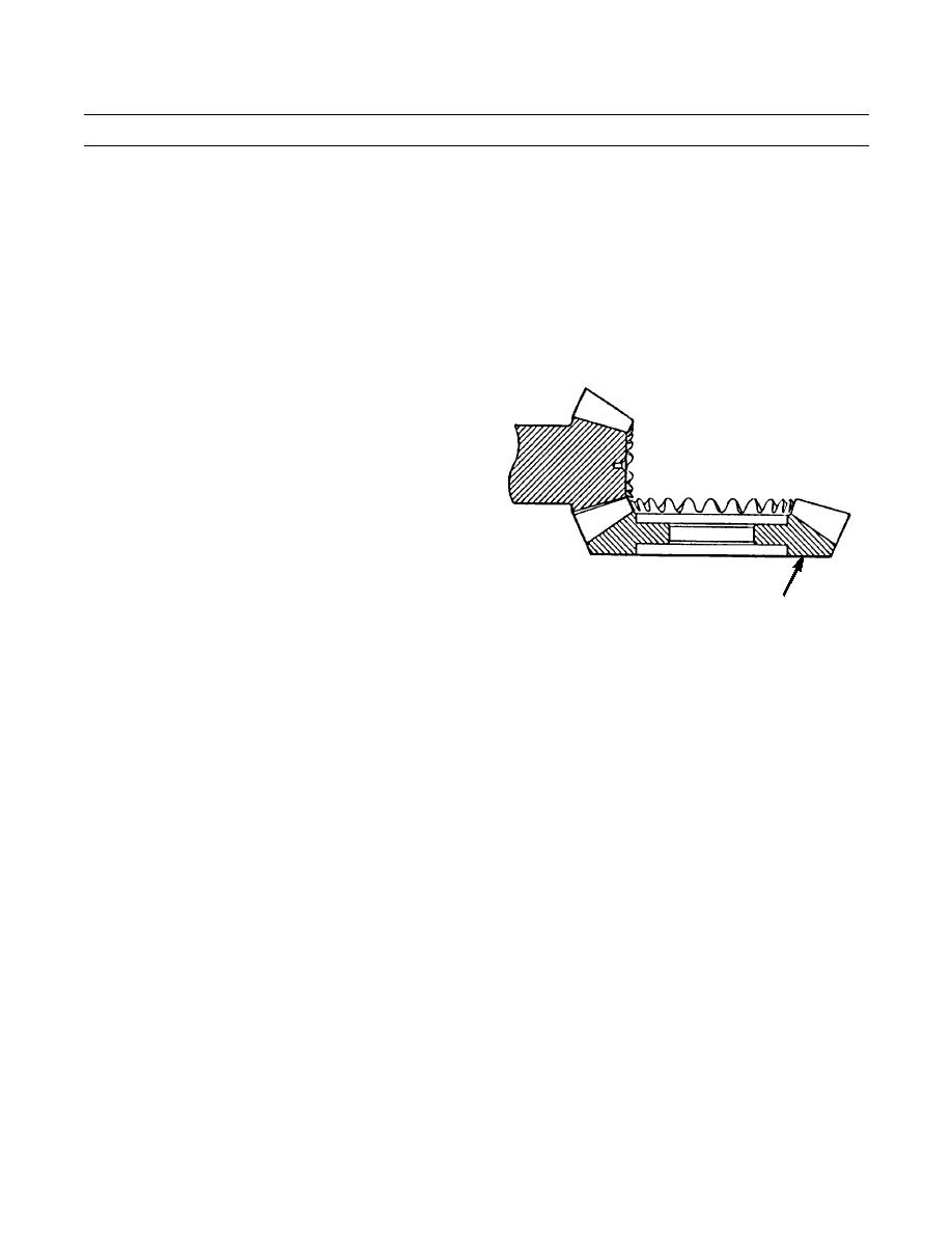
Make adjustments to bevel gear position for correct gear clearance (backlash) between bevel gear (16) and bevel pinion
(from transmission) as follows:
a.
Position magnetic based dial indicator so indicator tip contacts a tooth on bevel pinion.
b.
Wedge block of wood between bevel gear (16) and case so bevel gear will not turn.
NOTE
Ensure bevel pinion (from transmission) is held as far as possible toward front of machine when gear clear-
ance (backlash) is measured. Correct backlash is 0.015 in. + 0.004 in. or - 0.003 in. (0.38 mm + 0.10 mm or -
0.08 mm).
c.
Push bevel pinion toward front of machine as far
as possible. Move bevel pinion clockwise and
then counterclockwise. The free movement
(backlash) will be the difference in values read
on dial indicator.
d.
Repeat steps b and c at three more points around
bevel gear (16) to find point of smallest gear
clearance (backlash).
387-454
16
NOTE
Adjustment of bearings for bevel gear shaft (19) will not change by movement of shims from one bearing
cage to other bearing cage as long as total thickness of shims is the same.
e.
If measurement of smallest gear clearance (backlash) is too large, remove some of shims (22) from behind bearing
cage (14). Install shims (that were removed) behind bearing cage (15).
f.
If measurement of smallest gear clearance (backlash) is too small, remove some of shims (22) from behind bearing
cage (15). Install shims (that were removed) behind bearing cage (14).
7.
After bevel gear bearing preload and gear clearance (backlash) adjustments have been made, check tooth contact setting
between bevel gear (16) and bevel pinion shaft as follows:
a.
Apply thin coat of prussian blue on bevel gear teeth. Turn bevel pinion shaft and check marks made on bevel gear
teeth.
0127 00-9
|
|
Privacy Statement - Press Release - Copyright Information. - Contact Us |
