 |
|||
|
|
|||
|
|
|||
| ||||||||||
|
|
 TM 5-2410-237-23
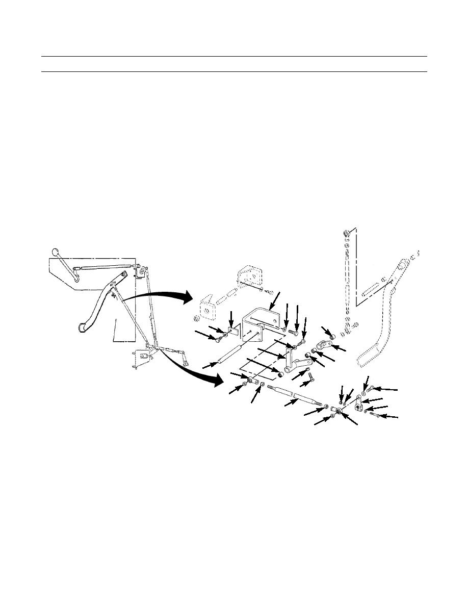
GOVERNOR CONTROLS AND LINKAGE MAINTENANCE - CONTINUED
0058 00
INSTALLATION - CONTINUED
13.
Install bracket (60) on flywheel housing with three capscrews (66) and washers (67).
14.
Install two bearings (62) in bellcrank (54).
15.
Install two bearings (63), nut (65) and capscrew (64) in bellcrank (39). Do NOT tighten nut.
16.
Install bellcrank (39 and 54) in bracket (60) with shaft (61).
17.
Install lock (59) on side of bracket (60) with capscrew (57) and washer (58) to secure shaft (61).
18.
Install lever (52) on shaft of governor with capscrew (51), two washers (50) and nut (49).
19.
Install two jam nuts (47) and rod ends (48) on rod (46). Adjust rod assembly length until distance between center line of
holes in rod ends is 17.24 in. (438 mm). See Adjustment, step 12. Tighten jam nuts against rod ends to secure.
20.
Install rod end (48) on bellcrank (39) with capscrew (44), two washers (45) and nut (43).
21.
Repeat step 20 for other rod end (48) on lever (52).
DASH
60
AREA
67 66
59
DASH
44
ASSY
62
58
57
45
39
MOUNTED ON
54
63
FLYWHEEL
62
HOUSING
61
63
45
48
MOUNTED ON
49 50
65
GOVERNOR
64
44
43
52
50
47
46
51
47
48
43
387-430
0058 00-7
|
|
Privacy Statement - Press Release - Copyright Information. - Contact Us |
