 |
|||
|
|
|||
|
Page Title:
Carrier Roller Support Assembly |
|
||
| ||||||||||
|
|
 NOTE
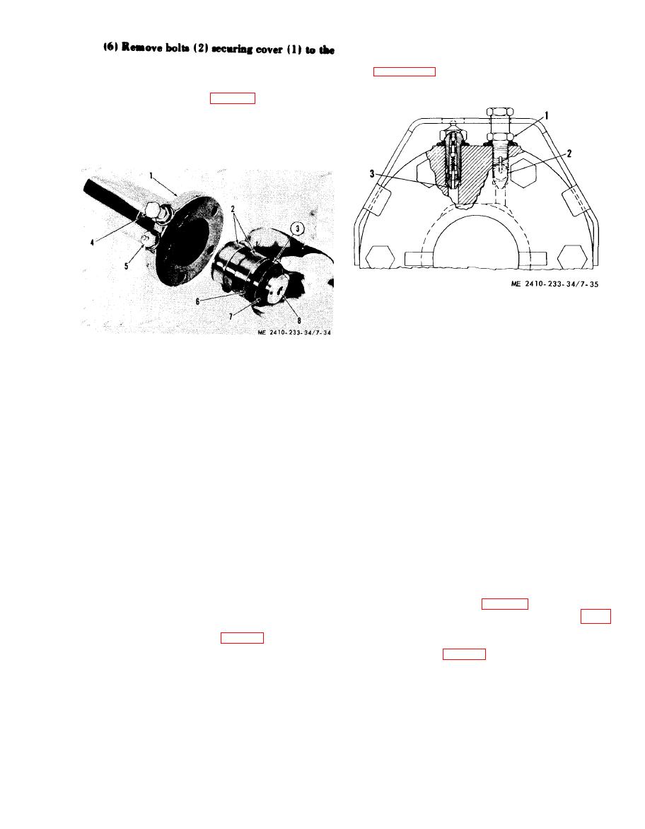
recoil spring front pilot. Pu1l the cylinder out of the
The torque values for valve (1) and (3) are given in
bore. Packing will come out with the cylinder.
justments as outlined in TM 5-2410-233-20.
b. Disassembly.
(1) Push piston (8, fig. 7-34) out of cylinder
(1).
(2) Inspect packing (3) and rings (2).
(3) Remove packing (3) and washer (6) after
removing snapring (7).
1 Relief valve
2 Vent hole
3 Fill valve
5 Fill valve
1
Cylinder
6 Washer
2
Rings
7 Snapring
3
Packing
a . Removal.
8 Piston
4
Relief valve
WARNING
Be certain the hydraulic pressure in the
track adjusting mechanism is com-
c. Reassembly.
pletely relieved and the cylinder can be
(1) Install packing with the lip toward
moved to the rear into the recoil spring
snapring (7).
front pilot before attempting to separate
(2) Lubricate the inside of cylinder (1) and
the track or remove the track adjusting
install piston assembly.
mechanism. On tractors that have badly
d. Installation. Install in reverse order of
w o r n track, it is possible for the
removal, rotating the cylinder so the flat (or guard)
hydraulic track adjuster to be adjusted
on the recoil rod flange aligns with the flat on the
forward to the limit of its travel and the
cylinder. Install the adjusting mechanism. Install
stop will be against the equalizer bar
and adjust the track ( e below).
support. The hydraulic cylinder could
e. Track Adjustment.
have high oil pressure in it even though
NOTE
the track is loose enough to remove the
Operate the tracks without excessive tension to
master pin without relieving the
minimize wear. When properly adjusted there should
be 1-inch to 1 inch sag measured at a point half way
hydraulic track adjusting pressure.
between the track carrier roller and front idler.
(1) Remove guards (fig. 7-25).
(1) Raise the inspection plate on the track
(2) Separate the track and iay it out flat (para
roller frame guard.
7-1).
(2) With relief valve (1, fig. 7-35) opened one
(3) Raise the front of the tractor until
turn counterclockwise, force GAA lubricant
equalizer bar (3, fig. 7-36) is against roil bar (2).
through fitting in fill valve (3).
Use blocking to support the front of the tractor.
(3) When the grease coming out vent hole (2)
(4) Remove bolts (4).
front the opened relief valve (1) is thick, close the
(5) Attach a hoist to and remove track carrier
relief valve and continue filling with lubricant until
roller (1, carrier roller bracket (6) and support
the track has 1-inch to 1 inch sag.
assembly (5) as a unit.
(4) Operate the machine backward and for-
ward to equalize the adjustment. Recheek ad-
justment.
|
|
Privacy Statement - Press Release - Copyright Information. - Contact Us |
