 |
|||
|
|
|||
|
Page Title:
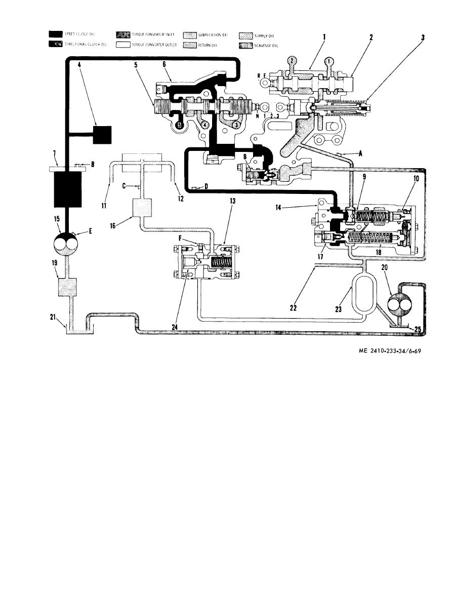
Figure 6-69. Transmission hydraulic control system schematic (First forward). |
|
||
| ||||||||||
|
|
 1
8
Load piston
Directional valve body
1
1
9
2
Magnetic
strainer
Directional vavle spool
2
0
3
Scavenge oil pump
Safety valve
4
2
1
Oil pump
Steering clutch controls
5
2
2
Lubrication line to bevel gear and
Speed selector valve spool
6
bevel pinion
Speed selector vavle body
7
23
T o r q u e divider
Oil filter
24
Torque divider oulet relief valve spool
Torque divider ratio valve spool
8
25
Pressure differential valve spool
Torque divider oil sump
9
A
Directional clutch oil pressure tap
C h e c k valve
10
T r a n s m i s s i o n oil filter pump pressure
B
11
Lubrication line to rear of transmission
tap
12
Lubrication line to front of transmission
Lubrication oil pressure tap
C
13
Torque divider outlet relief valve
D
14
Speed clutch oil pressure tap
Pressure control valve body
E
Transmisson oil pump pressure tap
F
Torque divider outlet oil pressure tap
Pressure modulating relief valve spool
|
|
Privacy Statement - Press Release - Copyright Information. - Contact Us |
