 |
|||
|
|
|||
|
Page Title:
Section Il. HYDRAULIC CONTROL VALVES AND HYDRAULIC PUMP |
|
||
| ||||||||||
|
|
 c. Cleaning. Flush and clean inside of hydraulic
tank with cleaning solvent (Fed. Spec. P-D-680).
Wipe outside of tank with a cloth dampened with
cleaning solvent. Wipe dry using a lint-free cloth.
d. Inspection.
( 1 ) Inspect hydraulic tank for cracks, breaks,
dents, broken welds, and corrosion. Tank will be
free of major denta and distortion that will affect
serviceability, capacity or appearance. Replace a
tank that is uneconomical to repair.
(2) Inspect hydraulic tank cap, gasket,
strainer, gage, filter springs, seat, and filter by-pass
v a l v e f o r d a m a g e o r d i s t o r t i o n . R e p l a c e all
defective parts.
e. Repair, Weld minor cracks and broken welds
p e r TM 9-237. Paint welded and other barren
a r e a s per TM 9-213.
f. R e a s s e m b l y a n d I n s t a l l a t i o n . R e v e r s e
disassembly and removal procedure and reassemble
a n d install the hydraulic tank on the tractor.
Replace all damaged gaskets and seals.
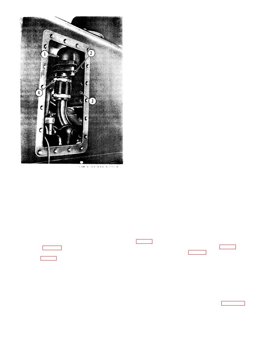
ME 2410-233-34/4-3
1 Filter inlet oil line
2 Bolts
3 Oil filter
4 Hose clamp
Section Il. HYDRAULIC CONTROL VALVES AND HYDRAULIC PUMP
4-3. Bulldozer Control Valve
b. Valve Spool Removal.
(1) Remove and inspect plug assemblies (2,
a. Removal.
(1) Remove the hydraulic control tank from
the end of the plugs engage detent (1, fig. 4-5) to
the tractor (para 4-2).
hold valve spool (4, fig. 4-5) in the FLOAT
(2) Remove the tank a s s e m b l y f r o m b o t t o m
plate ((6), fig. 4-4).
position.
(3) Remove bolts (3 and (14) and remove oil
(2) Remove bolt and lockwasher (5).
line (5).
CAUTION
(4) Disconnect rod (4) from end of control
Valve body (3) and spool (4) are
v a l v e spool-
machined to close tolerances. To avoid
(5) Remove bolt (9 and remove oil line (1).
d i s t o r t i o n of spool (4), leave spool in
( 6 ) Remove bolts (7) and (8) and remove
valve body when loosening or
elbows (10) and (11).
tightening bolt (5).
(7) Remove bolts (12) and remove bulldozer
(4) Disassemble spool as shown in figure 4-6.
c o n t r o l valve (2). The bulldozer control valve
weighs approximately 70 pounds,
|
|
Privacy Statement - Press Release - Copyright Information. - Contact Us |
