 |
|||
|
|
|||
|
Page Title:
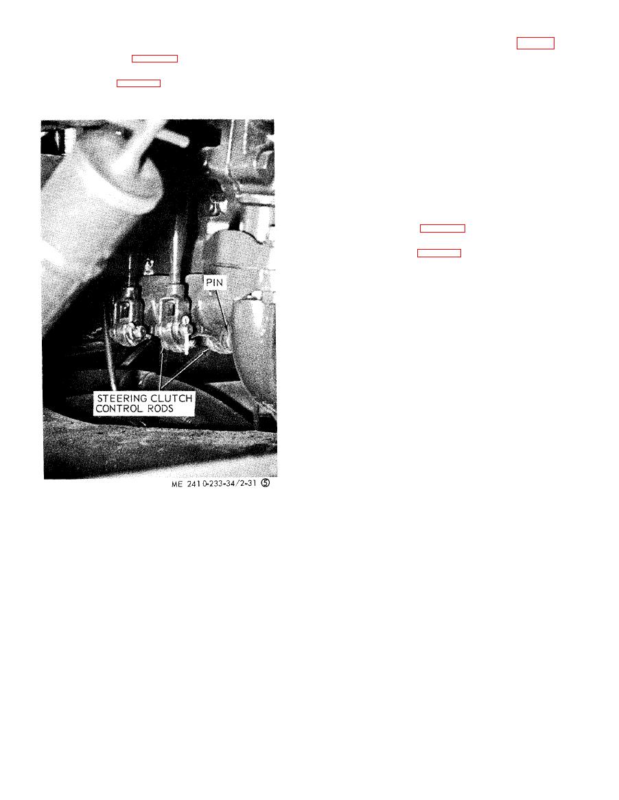
Figure 2-31. Preparing to remove engine (sheet 5 of 6). |
|
||
| ||||||||||
|
|
 (16) Remove the transmission vent line (fig. 2-
( 1 4 ) Disconnect the oil cooler oil outlet line
31, sheet 4).
f r o m t h e oil cooler (fig. 2-31, sheet 3).
(17) Remove oil pressure line from engine and
(15) Disconnect the steering clutch control
transmission.
rods at both ends (fig. 2-31, sheet 5) and slide the
(18) Remove
8
capscrews
and
remove
the
rods toward the rear of tractor.
drive shaft.
(19) Disconnect oil temperature
sensing
line
from the torque divider.
(20) Remove
the
transmission
oil
pump
oil
outlet line.
(21) Disconnect the oil outlet line from the
scavenge pump.
(22) Disconnect the torque divider oil supply
line from the torque divider.
(23) Remove the two engine front support to
frame mounting bolts (fig. 2-31, sheet 1).
(24) Remove the four engine rear support-to
frame mounting bolts (fig. 2-31, sheet 6). Remove
the two dash support brace mounting bolts.
Figure 2-31. Preparing to remove engine (sheet 5 of 6).
|
|
Privacy Statement - Press Release - Copyright Information. - Contact Us |
