 |
|||
|
|
|||
|
|
|||
| ||||||||||
|
|
 TM 10-3930-633-34
(2) Install bowl cover and new gasket.
with nuts and lockwashers. Tighten axle shaft
Tighten screws to 25 ft/lbs.
flange nuts to 52 -57 ft/lbs.
(3) Install bearing cups into wheel hub.
(7) Install as outlined in Chapter 2, Section
Install inner seal and slinger.
IV, and refill differential and drop gearcase with
(4) Secure hub to drum with studs and nuts.
proper oil (LO 10-3930-633-12).
Pack bearings with lubricant (LO 10-3930-633-12
and TM 10-3930-633-12).
a. Removal. Refer to paragraph 10-2 for
(5) Install hub and drum to axle housing.
removal instructions.
Install bearing nuts and nut lock and adjust
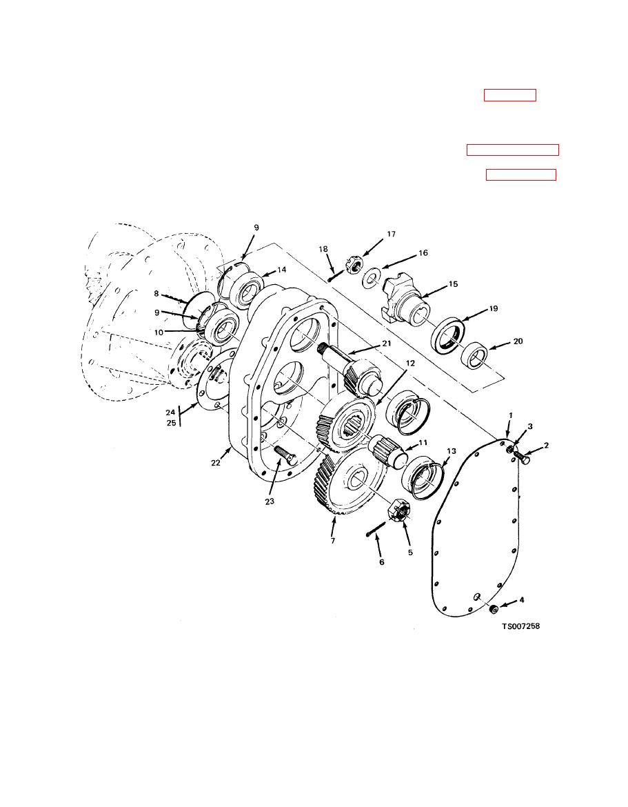
b. Disassembly. Refer to figure 10-5 and
bearings as outlined in TM 10-3930-633-12.
proceed as follows:
(6) Slide axle shaft into place, and secure
Washer
11. Shaft
16.
21. Gear
1. Cover
6. Pin
17.
Nut
22. Case
12. Gear
2. Screw
7. Gear
Pin
13. Ring
18.
23. Capscrew
3.Lockwasher
8. Plug
Seal
24. Gasket
19.
14. Bearing
4. Plug
9. Retaining ring
25. Gasket
20.
Spacer
10. Bearing
15. Flange
5. Nut
(2) Remove cotter pin (6) and nut (5). Pull
Remove thirteen cover screws (2) and
(1)
lockwashers (3) and lift off cover (1).
off gear (7).
|
|
Privacy Statement - Press Release - Copyright Information. - Contact Us |
