 |
|||
|
|
|||
|
Page Title:
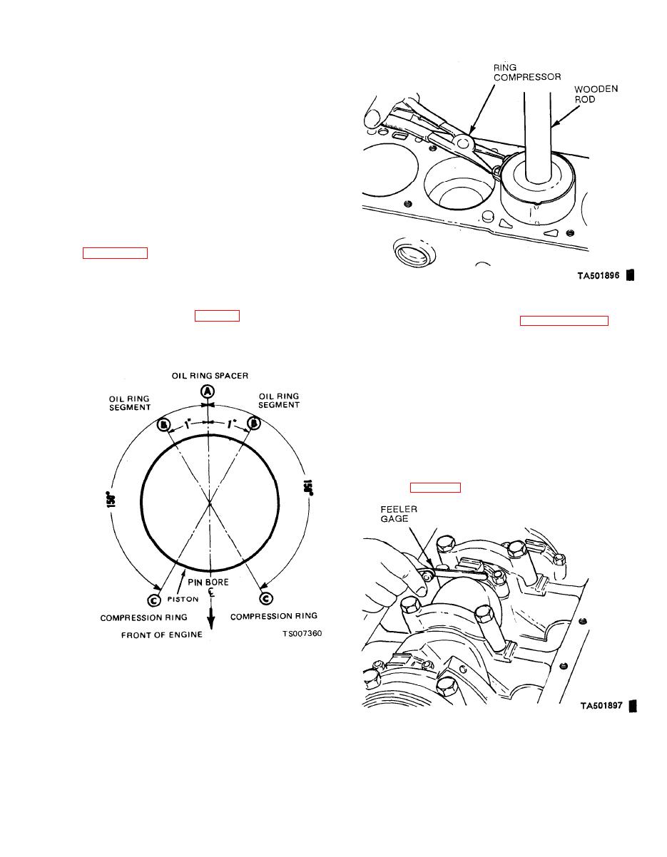
Figure 6-31. Piston Ring Gap Spacing. |
|
||
| ||||||||||
|
|
 TM 10-3930-633-34
(3) Be sure to install the pistons in the same
cylinders from which they were removed or to
which they were fitted. The connecting rods and
bearing caps are numbered from 1 to 6 beginning
at the front of the engine. The number on the
connecting rod and bearing cap must be on the
same side of rod when installing in the cylinder
bore. If a connecting rod is ever transferred from
one cylinder block to another or from one cylinder
to another, new bearings should be fitted and the
connecting rod s h o u l d be renumbered to
correspond with the new cylinder number.
(4) Make sure the ring gaps are properly
spaced around the circumference of the piston
ring compressor on the piston. Make sure that the
indentation in the head of piston is toward the
front, then push the piston into its bore with the
handle end of a hammer until it is slightly below
(5) Check the clearance of each bearing
the top of the cylinder (fig. 6-32). Be sure to guide
following the procedure under paragraph 6-33,
the connecting rods to avoid damaging the
Connecting Rod Bearing Replacement.
crankshaft journals.
(6) After the bearings have been fitted, apply
a light coat of engine oil to the journals and
bearings.
(7) Turn the crankshaft throw to the bottom
of its stroke, then push the piston all the way
down until the connecting rod bearing seats on
the crankshaft journal. Install the connecting rod
cap. Torque the nuts to specifications.
(8) After the piston and connecting rod
assemblies have been installed, check the con-
necting rod side clearance on each crankshaft
journal (fig. 6-33 ). Side clearance should be
0.0060 to 0.0130 inches.
|
|
Privacy Statement - Press Release - Copyright Information. - Contact Us |
