 |
|||
|
|
|||
|
|
|||
| ||||||||||
|
|
 TM 10-3930-633-12
b. Rear Wheels.
a. Removal.
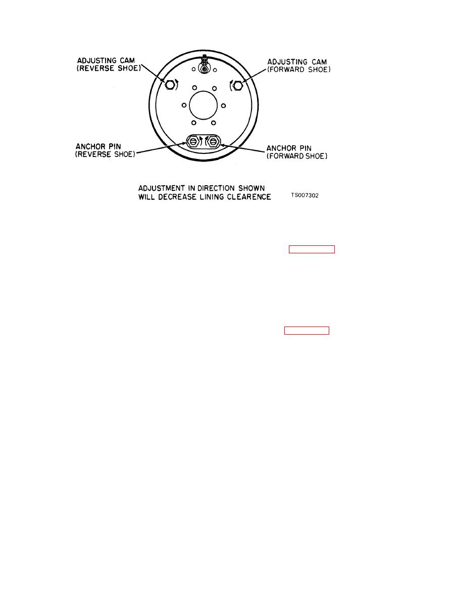
(1) To decrease clearance at anchor end of
forward shoe, turn forward shoe anchor pin in
front and rear brakes hydraulic lines at the outlet
direction illustrated by arrow.
fittings on the side of the master cylinder.
(2) To increase clearance at anchor end of
CAUTION
forward shoe, turn forward shoe anchor pin in
Plug, tape or otherwise seal the exposed
opposite direction indicated by arrow.
ports in the open end of the tube fittings
(3) Alternate between the anchor pin and the
to prevent contamination of the system.
adjusting cam until brake shoe feeler gage (.010
(2) Remove the nuts and lockwashers on the
in.) just fits between the drum and lining at both
studs extending through the master cylinder
"heel" and "toe." Then tighten the anchor pin
mounting flange (figure 4-49).
locknut.
(3) Remove the master cylinder from the
(4) Repeat this same procedure at the op-
power booster section.
posite shoe and on the other brake assembly.
|
|
Privacy Statement - Press Release - Copyright Information. - Contact Us |
