 |
|||
|
|
|||
|
Page Title:
Figure 4-18. Instrument Panel and Gages |
|
||
| ||||||||||
|
|
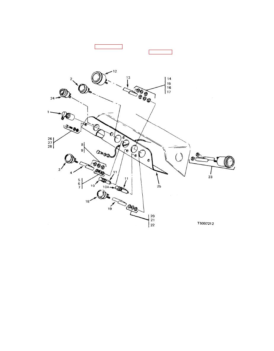 TM 10-3930-633-12
binding operation, damaged terminals, signs of
and their method of mounting in the instrument
overheating, damaged threads, and other
panel. Tag and disconnect wiring before removal
damage; replace damaged switches.
of any gage or switch. Reinstall as shown in figure
4-18. Wiring codes and connections are shown in
illustration showing all the gages and switches
1.
Ignition Switch
9. Washer
Nut
22.
15. Washer
10. Switch
Hourmeter
2.
Water temperature gage
23.
16. Nut
10A. Switch
24.
Transmission oil temperature gage
3.
Oil pressure gage
17. Nut
4.
Bracket
11. Switch
18. Ammeter
Instrument panel
25.
12. Fuel level gage
5.
Nut
Screw
26.
19. Bracket
13. Bracket
6.
Washer
Lockwasher
27.
20. Nut
7.
Nut
14. Nut
21. Washer
Nut
28.
8.
Nut
4-43. Lights and Horn
b. Stop and Taillight. The combination stop
and taillight is recessed behind the rear bumper
a. Headlights. The tractor is equipped with
plate and is mounted to the rear deck cover. This
two sealed-beam headlights, controlled by a push-
lamp has a dual-filament bulb. One filament is
p u l l switch on the instrument panel. The
illuminated whenever the headlight switch is on,
headlights are mounted in a metal bracket and
while the second filament is wired through the
recessed behind the front grille plate to provide
protection against breakage.
|
|
Privacy Statement - Press Release - Copyright Information. - Contact Us |
