 |
|||
|
|
|||
|
Page Title:
Figure 4-6. Ignition System Circuit |
|
||
| ||||||||||
|
|
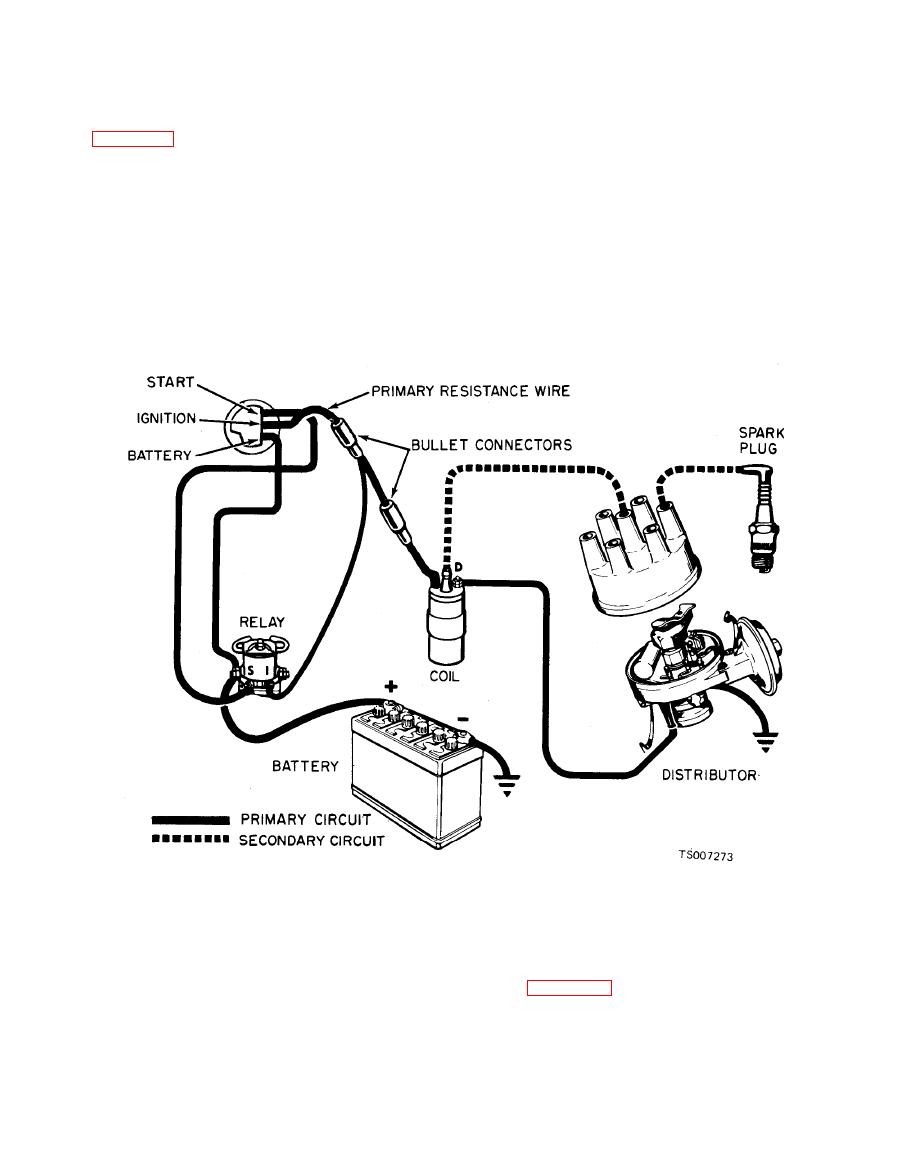 TM 10-3930-633-12
points. When the breaker points open, the
b. Ignition System. The ignition system
magnetic field built up in the primary windings of
consists of two separate circuits, a primary (low
the coil moves through the coil secondary wind-
voltage) and a secondary (high voltage) circuit
i n g s , producing high voltage current. This
(see figure 4-6). The primary circuit consists of
current is produced each time the breaker points
the battery, ignition switch, primary circuit
open. This high voltage flows through the coil
resistance wire, primary coil windings, breaker
high tension lead to the distributor cap, where the
points and condenser. The secondary circuit
rotor distributes it to one of the spark plug ter-
coil windings,
consists
of the secondary
minals in the distributor cap. From the plug
distributor rotor, distributor cap, high tension
terminal the current flows through the secondary
wires and spark plugs.
wire to the spark plug, where the spark ignites the
c. Ignition System Operation. When the
air-fuel mixture in the combustion chamber. This
breaker points are closed, the primary or low
entire process is repeated during every power
voltage current flows from the battery through
stroke of the engine.
the ignition switch to the primary windings in the
coil, then to ground through the closed breaker
the transmission selector lever in any gear range
d. Starting System. The starting system
except Neutral (N). In addition, the vacuum
includes the starting motor and drive, starter
switch prevents starter engagement whenever the
engine is running. A diagram of the system is
neutral start switch, and time delay and vacuum
shown in Figure 4-7.
switches. The neutral start switch is normally
open to prevent energizing the starter relay with
|
|
Privacy Statement - Press Release - Copyright Information. - Contact Us |
