 |
|||
|
|
|||
|
|
|||
| ||||||||||
|
|
 TM 9-2320-360-34-2
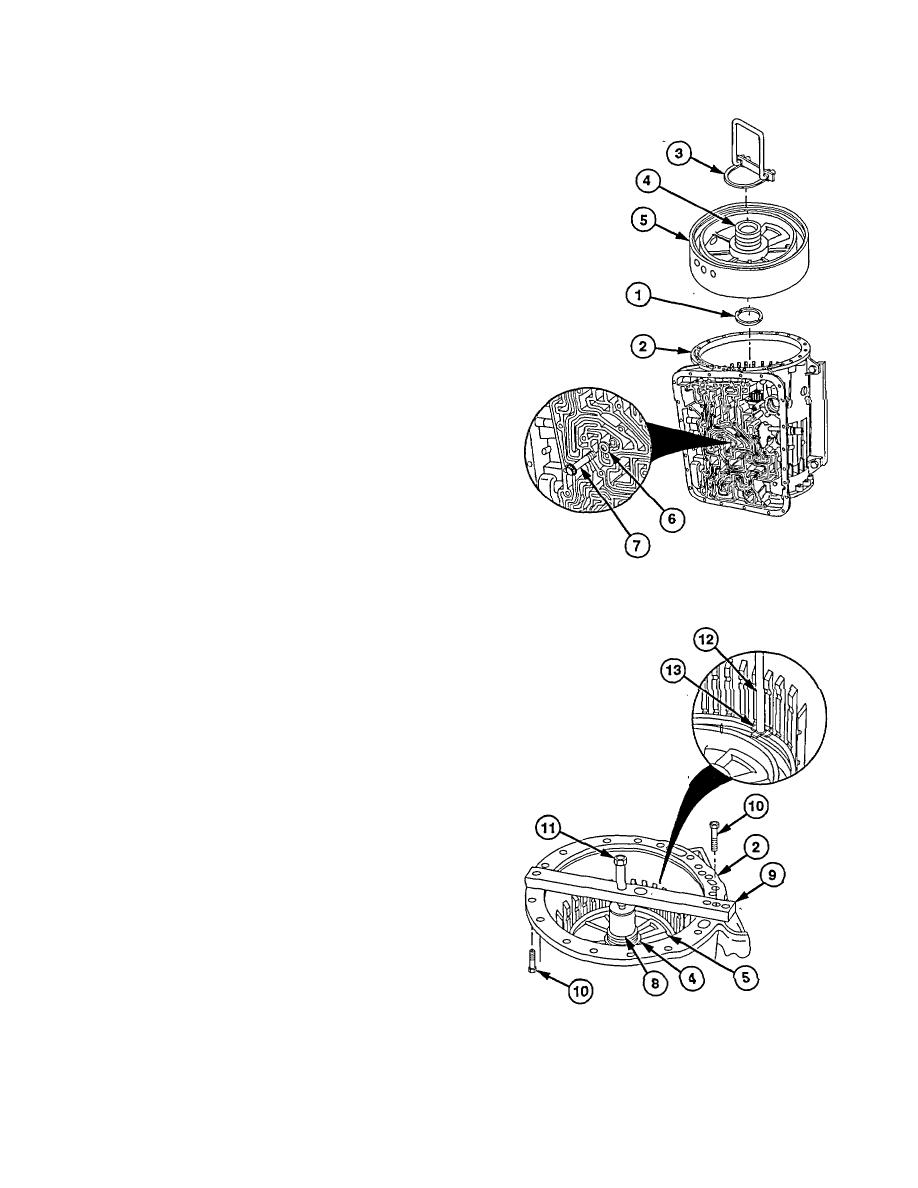
e. Installation
(1) Install thrust washer (1) in transmission
(2).
(2) Install lifting bracket (3) on center support
hub (4).
NOTE
Ensure tapped hole on center
support housing is aligned with hole
in transmission housing.
(3) Lower center support (5) into transmission
(2).
(4) Position washer (6) and anchor screw (7)
in transmission (2) and center support (5).
Do not tighten.
(5) Remove lifting bracket (3) from center
support hub J4).
(6) Install compressor sleeve (8) on hub (4) of
center support (5). Place compressor bar
(9) across transmission (2). install two
screws (10).
(7) Tighten compressor screw (11) to 60 lb-in.
(6.8 N m) to compress center support (5).
(8) Using retaining ring gage (12), measure
retaining ring opening with each of four
lugs (13). This will determine retaining
ring size.
(a) Blue color-coded ring is 0.1480.150
in. (3.76 to 3.81 mm thick).
(b) Yellow
color-coded
ring
is
0.1520.154 in. (3.86-3.91 mm) thick.
(c) White
color-coded
ring
is
0.1550.157 in. (3.94-3.99 mm) thick.
(d) Red color-coded ring is 0.1580.160
in. (4.01-4.06 mm) thick.
22-81
|
|
Privacy Statement - Press Release - Copyright Information. - Contact Us |
