 |
|||
|
|
|||
|
Page Title:
MAIN CONTROL VALVE REPAIR (CONT) |
|
||
| ||||||||||
|
|
 TM 9-2320-360-34-2
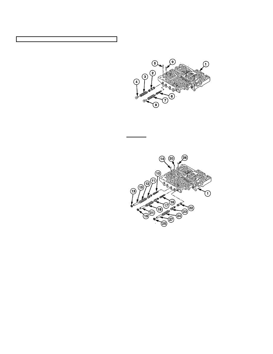
22-14. MAIN CONTROL VALVE REPAIR (CONT)
d. Assembly
(1) Place control valve body (1) on dean work
surface flat side up.
(2) Install trimmer regulator valve (2), valve
spring (3), and valve stop (4) in control
valve body (1).
(3) Press valve stop (4) and insert retaining
pin (5) in control valve body (1).
(4) Install four-five shift relay valve ( ), valve
6
spring (7), and valve stop (8) in control
valve body (1).
(5) Press valve stop (8) and insert retaining
pin (9) in control valve body (1).
CAUTION
Install adjusting rings in positions marked during removal. Improper shifting and possible
damage to transmission may result if not assembled to same notch.
(6) Install four-five shift signal valve (10), four-
five shift modulator valve (11), spring (12),
and adjusting ring (13) in control valve
body (1).
(7) Press adjusting ring (13) and insert
retaining pin (14) in control valve body (1)
far enough to hold adjusting ring in place.
(8) Install valve stop (15) in control valve body
(1). Install retaining pin (14) through hole
in valve stop (15).
(9) Install three-four shift signal valve (16),
three-four shift modulator valve (17), valve
spring (18), and adjusting ring (19) in
control valve body (1).
(10) Press adjusting ring (19) and insert
retaining pin (20) in control valve body (1)
far enough to hold adjusting ring in place.
(11) Install valve stop (21) in control valve body
(1). Install retaining pin (20) through hole
in valve stop (21).
(12) Install two-three shift signal valve (22),
two-three shift modulator valve (23), valve
spring (24), and adjusting ring (25) in
control valve body (1).
(13) Press adjusting ring (25) and insert
retaining pin (26) in control valve body (1)
far enough to hold adjusting ring in place.
(14) Install valve stop (27) in control valve body
(1). Install retaining pin (26) through hole
in valve stop (27).
22-70
|
|
Privacy Statement - Press Release - Copyright Information. - Contact Us |
