|
| |
TM 9-2320-360-34-1
e.
Installation
(1)
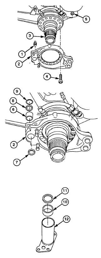
Install two grease fittings (1) in brake
bracket (2).
(2)
Position brake bracket (2) on spindle (3).
(3)
Install 10 sockethead screws (4) through
brake bracket (2).
(4)
Install 10 new locknuts (5) on screws (4).
Torque to 204 lb-ft (280 Nm).
(5)
Install bushing (6) in brake bracket (2).
CAUTION
· Outer seal must not be installed
any deeper than flush with spindle
assembly. Failure to comply will
cause grease leak and/or plugged
grease passage.
· All brake camshaft seals must be
installed with numbered side of
seal facing spindle and seal lips
facing away from spindle. Failure
to comply may result in seal
coming out of position and brakes
not releasing.
(6)
Install new outer seal (7), lip side first, in
brake bracket (2).
(7)
Install new inner seal (8), numbered side
first, in brake bracket (2).
(8)
Install new oil seal (9) in brake bracket (2).
NOTE
Bushing should be installed until it is
flush with inside machined land
surface.
(9)
Install bushing (10) and new seal (11),
numbered side first, in inner camshaft
mounting plate (12).
Change 1 11-11
|