|
| |
TM 9-2320-360-34-1
3-7.1. DDEC III SYNCHRONOUS REFERENCE SENSOR (SRS) AND TIMING
REFERENCE SENSOR (TRS) REPLACEM ENT/ADJUSTMENT (CONT)
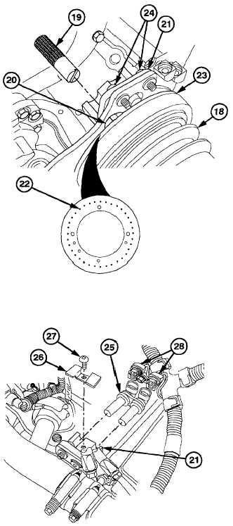
(11)
Tap end of camshaft pulley (18) with soft-
faced hammer to take up end play.
(12)
Insert alignment tool (19) in TRS sensor
hole (20) of bracket (21).
NOTE
There is a notch on the edge of the
pulse wheel next to the correct TRS
timing pin.
(13)
Move bracket (21) until notch in tool
engages with TRS timing pin (22) on pulse
wheel (23).
(14)
Tighten two sockethead screws (24) and
remove alignment tool (19).
(15)
Tap end of camshaft pulley (18) again to
take up end play.
(16)
Install SRS/TRS (25) in bracket (21) with
retaining clip (26) and screw (27). Do not
tighten.
NOTE
When properly adjusted, there should
be .018 .022 in. (.46 .56 mm) between
pulse wheel teeth and the end of the
sensor.
(17)
Position a .020 in. (.50 mm) feeler gage
between TRS sensor (25) and the TRS
pin on the pulse wheel (23).
(18)
Slide the SRS/TRS (25) against feeler
gage and tighten screw (27).
(19)
Connect two connectors (28) to SRS/TRS
(25).
3-64.4 Change 3
|