|
| |
TM 9-2320-360-34-1
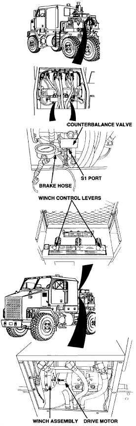
HYDRAULIC SYSTEM TEST
(1) Remove brake hose from S1 port on counterbalance
valve.
(2) Install tee, pressure gage and pressure hose on
counterbalance valve.
(3) Start engine and engage PTO and high idle
(TM 9-2320-360-10).
(4) Pull up or push down control valve lever, and
observe pressure.
(5) Release winch control lever, disengage high idle
and PTO, and shut engine off (TM 9-2320-360-10).
(6) Remove pressure hose, pressure gage and tee from
counterbalance valve.
(7) Install brake hose on S1 port of counterbalance
valve.
DRIVE MOTOR TEST
NOTE
· Winch hydraulic reservoir should beat
least warm to the touch and engine on
high idle during winch troubleshooting
· Winch assembly will leak gear oil when
drive motor is removed.
(1) Remove two screws, lockwashers and drive motor
from winch assembly with aid of assistant.
(2) Start engine and engage PTO and high idle
(TM 9-2320-360-1 0).
(3) Operate winch drive motor by pulling up and
pushing down on control lever while assistant
supports motor.
(4) Disengage high idle and PTO and shut off engine
(TM 9-2320-360-10).
NOTE
If results of troubleshooting indicate faulty
winch drive motor, do not do step (5)
(5) Install drive motor on winch assembly with two
new lockwashers and screws with aid of assistant.
Change 2 2-171
|