|
| |
TM 9-2320-360-34-1
17-5. DRIVE MOTOR REPLACEMENT
This task covers:
a. Removal
c. Follow-On Maintenance
b. Installation
INITIAL SETUP
Equipment Conditions
Materials/Parts
Counterbalance valve removed (para 17-4).
Adhesive-Sealant, Silicone (Item 2, Appendix B)
Lockwashers (2) (Item 130, Appendix F)
Tools and Special Tools
Tool Kit, Genl Mech (Item 202, Appendix E)
a.
Removal
NOTE
Both drive motors are replaced the
same way. Left side is shown.
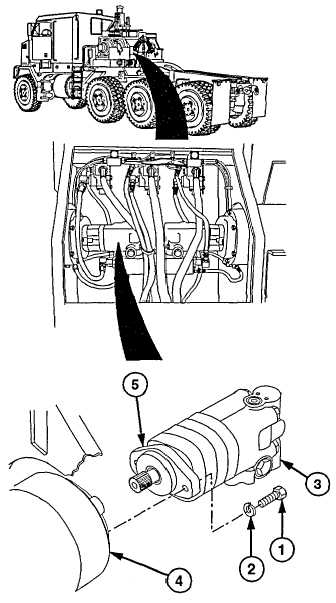
Remove two screws (1), lockwashers (2), and
drive motor (3) from winch assembly (4).
Discard lockwashers.
b.
Installation
WARNING
On direct contact, uncured silicone
sealant irritates eyes. In case of
contact, flush eyes with water and
seek medical attention. In case of
skin contact, wipe off and flush with
water.
(1)
Lightly coat edge of bearing housing (5)
on drive motor (3) with thin layer of
silicone adhesive-sealant.
(2)
Install drive motor (3) on winch assembly
(4) with two new lockwashers (2) and
screws (1).
c.
Follow-On Maintenance
Install counterbalance valve (para 17-4).
17-19
|