|
| |
TM 9-2320-360-34-1
15-5. REAR SUSPENSION ARM REPLACEMENT
This task covers:
a. Removal
c. Follow-On Maintenance
b. Installation
INITIAL SETUP
Equipment Conditions
Materials/Parts
Wheel/tire removed (TM 9-2320-360-20).
Adhesive-Sealant (Item 8, Appendix B)
Air system drained (TM 9-2320-360-10).
Beam Hanger Bolt Kit (Item 3, Appendix F)
Shock absorbers removed (axle no. 2 and
Bushing Bolt Kit (Item 4, Appendix F)
axle no. 3 only) (TM 9-2320-360-20).
Lockwashers (4) (Item 132, Appendix F)
Tools and Special Tools
Personnel Required
Tool Kit, Genl Mech (Item 202, Appendix E)
Two
Jack, Floor (Item 90, Appendix E)
Jackstand (Item 93, Appendix E)
Multiplier, Torque, 4000 lb-ft (Item 99,
Appendix E)
Wrench, Combination, 1-1/2 In. (Item 214,
Appendix E)
Wrench, Open-End, 1-7/8 & 1-11/16 In.
(Item 225, Appendix E)
Wrench Set, Socket, 3/4 In. Drive (Item 231,
Appendix E)
Wrench, Torque, 0-600 Lb-Ft (Item 233,
Appendix E)
a. Removal
WARNING
Do not work on any Item supported
only by Jack or hoist. Always use
jackstands or blocks to support any
Item prior to work. Equipment may
fall and cause Injury or death.
NOTE
· Right and left suspension arms are
replaced the same way. Right side is
shown.
· Axle should be level side to side for
easier removal.
(1)
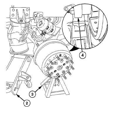
Lift axle housing (1) with jack (2) and support
with jackstand (3) at axle flange (4). Remove
floor jack (2).
15-18
|

