|
| |
TM 9-2320-360-34-1
(3)
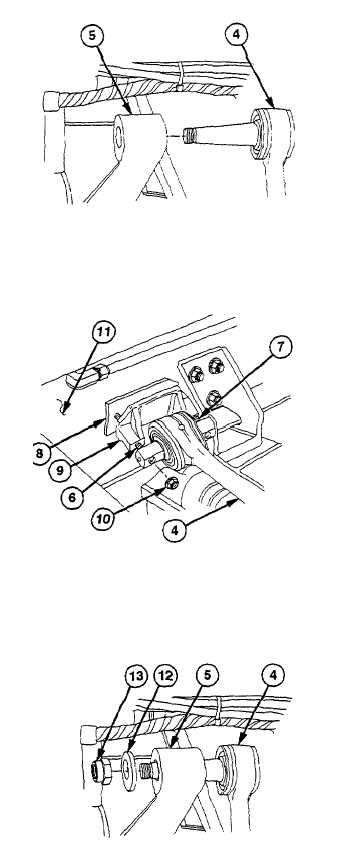
Position lateral torque rod (4) on axle (5).
NOTE
Ball stud taper and tapered bracket
hole must be free of all foreign matter
before assembly.
(4) Coat threads of screws (6 and 7) and lateral
torque rod (4) with lubricating oil.
NOTE
Number of spacers will vary.
Same number of spacers that were
removed must be installed.
(5) Install spacer(s) (8), bracket (9), lateral torque
rod (4), screw (6), screw (7), and two new
locknuts (10) on frame (11) with aid of assistant.
Torque to 212 Ib-ft (287 Nm).
(6) Install washer (12) and new locknut (13) on
lateral torque rod (4). Torque to 175-225 lb-ft
(237-305 Nm).
NOTE
Torque rod must be properly seated
in axle housing. Strike axle housing
at torque rod mounting point to seat
torque rod.
(7) Strike axle (5) with hammer and tighten locknut
(13) to 175-225 lb-ft (237-305 Nm).
15-13
|