|
| |
TM9-2320-360-20-3
Section 4
TROUBLESHOOTING CHARTS
E. FLASHCODE: 11
J1587 CODE:
P187 4 - POWER TAKE OFF INPUT FAILED LOW (VOLTAGE LOW)
(ALSO CALLED VARIABLE SPEED GOVERNOR - VSG)
STEP/SEQUENCE
RESULT
WHAT TO DO NEXT
11-5
Check Vernier
Control Connectors
l Inspect terminals at the vernier
control connectors (sensor side
and harness side) for damage;
bent, corroded, and unseated
pins or sockets.
11-6
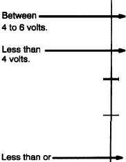
Check for +5 Volts
l Remove jumper.
l Turn ignition on.
l Read voltage on vernier control
connector, socket C (red lead)
to socket A (black lead).
11-7
Check for Short
l Turn ignition off.
l Disconnect the vehicle harness
connector ECM.
l Read resistance between sockets
A and B on the vernier control
connector.
11-8
Check for Signal Open
l Install a jumper wire between
sockets A and B of the vernier
control connector.
l Read resistance between sockets
D1 (510) & C3 (952) on the vehicle
harness connector.
Terminals and
connectors are okay.
Problem found.
Replace vernier control
(para 7-76). Then go to 11-30.
Repair terminals/connectors
(para 7-77). Then go to 11-30.
Go to
Go to
11-7.
11-10.
Greater than
Go to 11-12.
6 volts.
equal to 10,000 ohms.
Signal line (ckt #525) is shorted
to the return line (ckt #952).
Repair short. Then go to 11-30.
Go to 11-8.
Less than
or equal to 5 ohms.
Greater than
5 ohms or open.
Signal line (ckt #510) is open,
and/or signal return (ckt #952)
is open. Repair open. If no
open was found, check ECM
terminals A3, D1, C3, and vernier
control pins. Then go to 11-30.
H-105
|


