|
| |
TM 9-2320-360-20-1
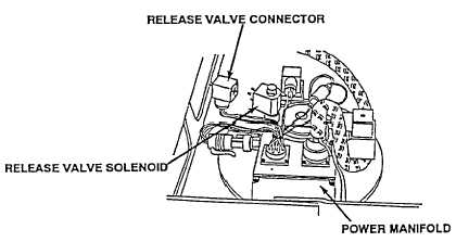
RELEASE VALVE VOLTAGE TEST
(1)
Disconnect release valve connector from
power manifold
(2)
Place positive (+) probe of multimeter on
release valve connector, pin 2.
(3)
Place negative (-) probe of multimeter
on known good ground
(4)
Turn engine switch to ON position
(TM 9-2320-360-10).
(5)
Move CTI switch to ON position
(TM 9-2320-360-10).
(6)
Press START button and look for 22-28
volts on multimeter
(7)
Turn engine switch to OFF position
(TM 9-2320-360-10).
(8)
Connect release valve connector to
power manifold
POWER MANIFOLD
GROUND CIRCUIT
CONTINUITY TEST
(1)
Disconnect release valve
connector from power manifold
(2)
Place positive (+) probe of
multimeter in release valve
connector, pin 1.
(3)
Place negative (-) probe of
multimeter on known good ground
and check multimeter for
continuity
(4)
Connect release valve connector
to power manifold
SOLENOID COIL TEST
(1)
Remove connector from
release valve solenoid.
(2)
Place positive probe (+) of
multimeter on release valve
solenoid pin 1.
(3)
Place negative probe (-) of
multimeter on release valve
solenoid pin 2 and look for
50-60 ohms on multimeter.
(4)
Install connector on release
valve solenoid
2-871
|