|
| |
TM 9-2320-360-20-1
WARNING
Jewelry can catch on equipment and cause injury or short
across electrical circuit and cause severe burns or electrical
shock. Remove rings, bracelets, watches, necklaces, and
any other jewelry before working around HET Tractor.
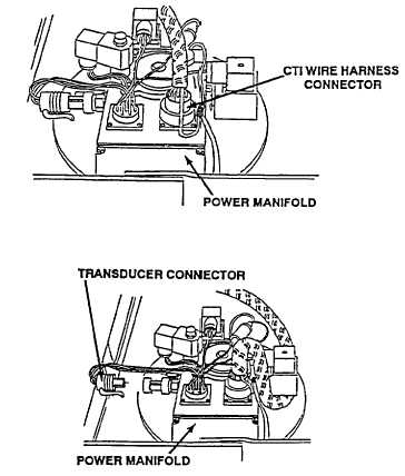
WIRE NO. 1065 VOLTAGE TEST
NOTE
CTI wiring harness must remain
Installed to controller and power
manifold when performing this test.
(1)
Turn engine switch to ON position
(TM 9-2320-360-10).
(2)
Move CTI switch to ON position (TM 9-2320-360-10).
(3)
Place positive (+) probe of multimeter on pin 10, wire
no 1065 (gray), of CTI wire harness connector at
power manifold.
(4)
Place negative (-) probe of multimeter on known good
ground
(5)
Press CTI START button (TM 9-2320-360-10) and
look for voltage on multimeter.
(6)
Turn engine switch to OFF position and move CTI
controller switch to OFF position (TM 9-2320-360-10).
POWER MANIFOLD
VOLTAGE TEST
(1)
Disconnect transducer connector.
(2)
Turn engine switch to ON position
(TM 9-2320-360-10)
(3)
Move CTI switch to ON position
(TM 9-2320-360-10)
(4)
Place positive (+) probe of
multimeter on black transducer
wire
(5)
Place negative (-) probe of
multimeter on known good ground
and look for 5 volts on multimeter.
(6)
Connect transducer connector.
POWER MANIFOLD GROUND
CIRCUIT CONTINUITY TEST
(1)
Disconnect transducer connector
from power manifold
(2)
Disconnect CTI wire harness
connector from power manifold
(3)
Place positive (+) probe of multimeter
on green pin of transducer connector
to power manifold
(4)
Place negative (-) probe of
multimeter on known good ground
and check multimeter for continuity
(5)
Connect CTI wire harness connector
on power manifold
(6)
Connect transducer connector to
power manifold.
2-867
|