|
| |
TM 9-2320-360-20-1
WARNING
Jewelry can catch on equipment and cause
injury or short across electrical circuit and cause
severe bums or electrical shock. Remove rings,
bracelets, watches, necklaces, and any other
jewelry before working around HET Tractor.
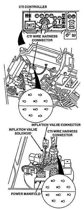
CTIS WIRE HARNESS CONTINUITY TEST
(1)
Disconnect CTIS wire harness connector from
power manifold
(2)
Disconnect CTIS wire harness connector from
controller.
NOTE
Pay special attention to position
7 and position 1.
(3)
Place positive (+) probe of multimeter on position
1 of connector at controller end.
(4)
Place negative (-) probe of multimeter on
position 1 of connector at power manifold end
and check multimeter for continuity.
(5)
Repeat steps (3) and (4) for remaining positions
2 thru 10.
(6)
Install CTIS wire harness connectors back on
power manifold and controller.
INFLATION VALVE VOLTAGE TEST
(1)
Disconnect inflation valve connector from power manifold.
(2)
Place positive (+) probe of multimeter on inflation valve
connector, position 2
(3)
Place negative (-) probe of multimeter on known good
ground
(4)
Turn engine switch to ON position (TM 9-2320-360-10)
(5)
Move CTIS switch to ON position (TM 9-2320-360-10)
NOTE
It is normal for voltage to fluctuate.
(6)
Press START button and look for 22-28 volts on
multimeter
(7)
Turn engine switch to OFF position (TM 9-2320-360-10).
(8)
Connect inflation valve connector to power manifold
INFLATION VALVE
SOLENOID COIL TEST
(1)
Remove connector from
inflation valve solenoid
(2)
Place positive probe (+) of
multimeter on inflation valve
solenoid pin 1.
(3)
Place negative probe (-) of
multimeter on inflation valve
solenoid pin 2 and look for
23-28 ohms on multimeter.
(4)
Install connector on inflation
valve solenoid.
Change 1 2-851.8
|