|
| |
TM 9-2320-360-20-1
TRANSDUCER VOLTAGE TEST
NOTE
·
Tire pressures must be between 20-30 psi (138-207
kPa) before beginning test to measure complete range
of transducer voltage output.
·
STE\ICE Test #50 is used to monitor pressures at
porting block.
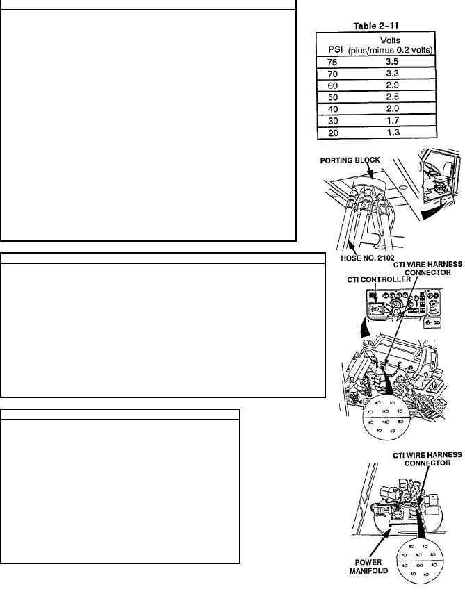
(1)
Remove hose no 2102 and elbow from porting block.
(2)
Install STE/ICE adapter and 0-1000 psi (0-6895 kPa) pressure
transducer on porting block
(3)
Set CTIS controller to HIGHWAY setting (TM 9-2320-360-10).
NOTE
CTIS wiring harness must remain Installed to controller
and power manifold when performing this test.
(4)
Place positive (+) probe of multimeter on position c (white) transducer
wire
(5)
Place negative (-) probe of multimeter on known good ground.
(6)
Start engine (TM 9-2320-360-10).
(7)
Move CTIS switch to ON position (TM 9-2320-360-10).
(8)
Press CTIS START button (TM 9-2320-360-10).
(9)
Record transducer voltage when porting block pressure reaches values
shown in Table 2-11.
(10) Shut off engine (TM 9-2320-360-10).
(11) Remove STE/ICE pressure transducer and adapter from porting block.
(12) Install elbow and air hose no. 2102 on porting block.
POWER MANIFOLD VOLTAGE TEST
NOTE
·
Tire pressures must be 75 psi (517 kPa) before
beginning test to measure correct transducer voltage
output
·
CTIS wiring' harness must remain installed to controller
and power manifold when performing this test.
(1)
Place positive (+) probe of multimeter on position 7, wire no 1062
(white), at controller.
(2)
Place negative (-) probe of multimeter on known good ground
(3)
Start engine (TM 9-2320-360-10),
(4)
Move CTIS switch to ON position (TM 9-2320-360-10).
(5)
Press CTIS START button (TM 9-2320-360-10) and look for 3.5 +/-.2
volts on multimeter.
(6)
Shut off engine (TM 9-2320-360-10).
CTIS WIRE HARNESS CONTINUITY TEST
(1)
Disconnect CTIS wire harness connector from
power manifold
(2)
Disconnect CTIS wire harness connector from
controller.
NOTE
Pay special attention to pin 7.
(3)
Place positive (+) probe of multimeter From position 1
of connector at controller end.
(4)
Place negative (-) probe of multimeter on position
1 of connector at power manifold end and check
multimeter for continuity.
(5)
Repeat steps (3) and (4) for remaining positions 2
thru 10
(6)
Install CTIS wire harness connectors back on
power manifold and controller
Change 1 2-839
|