|
| |
TM 9-2320-360-20-1
WARNING
Jewelry can catch on equipment and cause
injury or short across electrical circuit and cause
severe burns or electrical shock. Remove rings,
bracelets, watches, necklaces, and any other
jewelry before working around HET Tractor.
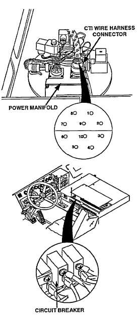
POWER MANIFOLD VOLTAGE TEST
NOTE
CTIS wiring harness must remain
installed to controller and power manifold
when performing this test
(1)
Turn engine switch to ON position (TM 9-2320-360-10)
(2)
Move CTIS switch to ON position (TM 9-2320-360-10)
(3)
Place positive (+) probe of multimeter on position 9, wire
no. 1064 (orange), of CTIS wire harness connector at
power manifold.
(4)
Place negative (-) probe of multimeter on known good
ground and look for 13-14 volts on multimeter
(5)
Turn engine switch to OFF position and move CTIS
controller switch to OFF position (TM 9-2320-360-10)
CIRCUIT BREAKER TEST
(1)
Remove eight screws and panel
from electric control box.
(2)
Turn engine switch to ON position
(TM 9-2320-360-10).
(3)
Place positive (+) probe of
multimeter on lower terminal of
circuit breaker.
(4)
Place negative (-) probe of
multimeter on ground and look for
22-28 volts on multimeter
(5)
Turn engine switch to OFF position
(TM 9-2320-360-10).
Change 1 2-829.2
|