|
| |
TM 9-2320-360-20-1
WARNING
·
Batteries
must
be
disconnected
before tightening any connections.
Failure to comply may result in injury
to personnel.
·
Remove all jewelry such as rings,
dog tags, bracelets, etc. If jewelry
contacts electrical terminals a direct
short may result in an instant heating
of tools, damage to equipment, and
injury to personnel.
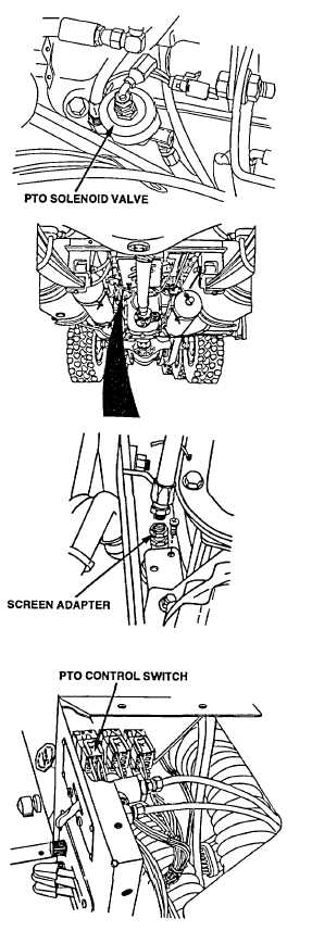
Check ground wire no. 1435 from PTO solenoid valve
for loose connections, damage, and continuity.
CONTINUITY TEST
(1)
Disconnect wiring from components at each
end of wire.
(2)
Set multimeter to ohms position.
NOTE
A reading of infinity indicates
an open circuit.
(3)
Connect multimeter leads to each end of wire
and check multimeter for continuity.
NOTE
A reading of other than infinity
indicates a grounded wire.
(4)
Remove multimeter lead from one end of wire
and connect to chassis ground.
SCREEN ADAPTER CHECK
(1)
Place drain pan under PTO solenoid.
(2)
Remove hose no 2851 from screen adapter.
(3)
Remove screen adapter from elbow.
(4)
Inspect screen adapter for restriction, foreign
material or damage.
NOTE
If screen adapter is OK, do
not perform steps (5) and (6).
(5)
Install screen adapter on elbow.
(6)
Install hose no. 2851 on screen adapter.
WIRE NO. 1719A VOLTAGE
TEST
NOTE
Engine must be running
to perform this test.
(1)
Place positive (+) probe of multimeter
on wire no. 1719A at PTO control switch.
(2)
Place negative (-) probe of multimeter
on ground and look for 22-28 volts on
multimeter.
Change 2 2-687
|

