|
| |
TM 9-2320-360-20-1
VISUAL INSPECTION
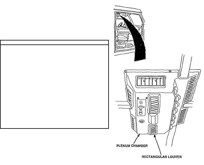
NOTE
· There are two blower fan motors
contained within the ventilator. One
motor operates the two blower wheels
on the driver's side, the other motor
operates the two blower wheels on
the passenger's side.
· The rectangular louvers are removed
for access to troubleshooting test
points, while allowing the ventilator to
remain operational.
(1)
Remove six rectangular louvers from plenum
chamber.
(2)
Turn engine switch to ON position.
(3)
Operate ventilator on high (H), medium (M), and low
(L) (TM 9-2320-360-10) and check the operation of
the passenger and driver side blower wheels
(4)
Turn engine switch to OFF position.
(1)
Turn engine switch to ON position.
(2)
Operate ventilator on high (H), medium (M),
and low (L) (TM 9-2320-360-10) and check
the operation of the faulty blower fan motor.
(3)
Turn engine switch to OFF position.
Change 1 2-628.3
|