|
| |
TM 9-2320-360-20-1
WARNING
Jewelry can catch on equipment
and cause injury or short across
electrical
circuit
and
cause
severe burns or electrical shock.
Remove
rings,
bracelets,
watches, necklaces, and any
other jewelry before working
around HET Tractor.
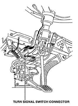
WIRE NO. 1080 VOLTAGE TEST
(1)
Turn ENGINE switch to ON position.
(2)
Place positive (+) probe of multimeter
on wire no. 1080 at turn signal switch.
(3)
Place negative (-) probe of multimeter
on ground and look for 10-14 volts on
multimeter.
(4)
Turn ENGINE switch to OFF position.
TURN SIGNAL SWITCH TEST (RIGHT TURN)
(1)
Turn ENGINE switch to ON position.
(2)
Place turn signal switch in right turn position.
NOTE
Wire no. 1001 operates right turn signal
indicator and right front turn signal.
(3)
Place positive (+) probe of multimeter on wire no. 1001 at
turn signal switch.
(4)
Place negative (-) probe of multimeter on ground and look
for 10-14 volts on multimeter.
NOTE
Wire no. 1004 operates right rear turn signal.
(5)
Place positive (+) probe of multimeter on wire no. 1004 at
turn signal switch.
(6)
Place negative (-) probe of multimeter on ground and look
for 10-14 volts on multimeter.
(7)
Place turn signal switch in off position.
(8)
Turn ENGINE switch to OFF position.
TURN SIGNAL SWITCH TEST (LEFT TURN)
(1)
Turn ENGINE switch to ON position.
(2)
Place turn signal switch in left turn position.
NOTE
Wire no. 1002 operates left turn signal
indicator and left front turn signal.
(3)
Place positive (+) probe of multimeter on wire no. 1002 at
turn signal switch.
(4)
Place negative (-) probe of multimeter on ground and look
for 10-14 volts on multimeter.
NOTE
Wire no. 1003 operates left rear turn signal.
(5)
Place positive (+) probe of multimeter on wire no 1003 at
turn signal switch.
(6)
Place negative (-) probe of multimeter on ground and look
for 10-14 volts on multimeter.
(7)
Place turn signal switch in off position.
(8)
Turn ENGINE switch to OFF position.
Change 2 2-541
|