|
| |
CONTINUITY TEST
CAUTION
Electrical power must be disconnected from circuit
before continuity can be checked failure to comply may
result in damage to test equipment or electrical system.
(1)
Disconnect wiring from components at each end of
wire.
(2)
Set multimeter to ohms position.
NOTE
A reading of infinity indicates an open circuit.
(3)
Connect multimeter leads to each end of wire and
check multimeter for continuity.
NOTE
Any reading besides infinity indicates a grounded wire
(4)
Remove multimeter lead from one end of wire and
connect to chassis ground
TM 9-2320-360-20-1
WARNING
Jewelry can catch on equipment and cause Injury or short
across electrical circuit and cause severe burns or electrical
shock. Remove rings, bracelets, watches, necklaces, and
any other jewelry before working around HET Tractor.
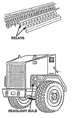
Check ground wire no. 1435 from HEAD LTS
relay for loose connections or damage.
DIMMER RELAY TEST
(1)
Turn ENGINE switch to ON position
(2)
Place headlights switch in the on position
(3)
Place headlight dimmer switch in the low beam
position
(4)
Place positive (+) probe of multimeter on wire no.
1435 at DIMMER relay
(5)
Place negative (-) probe of multimeter on ground and
look for 10-14 volts on multimeter.
(6)
Place positive (+) probe of multimeter on wire no.
1006 at DIMMER relay
(7)
Place negative (-) probe of multimeter on ground and
look for 10-14 volts on multimeter.
(8)
Place headlight dimmer switch in the high beam
position
(9)
Place positive (+) probe of multimeter on wire no.
1007 at DIMMER relay
(10) Place negative (-) probe of multimeter on ground and
look for 10-14 volts on multimeter.
(11) Place headlights switch in the off position.
(12) Turn ENGINE switch to OFF position
WIRES NO. 1006 & NO. 1007
VOLTAGE TEST
(1)
Turn ENGINE switch to ON position
(2)
Place headlights switch in the on position
(3)
Place headlight dimmer switch in the
low beam position
(4)
Place positive (+) probe of multimeter
on wire no 1006 at headlights
(5)
Place negative (-) probe of multimeter
on ground and look for 10-14 volts on
multimeter.
(6)
Place headlight dimmer switch in the
high beam position.
(7)
Place positive (+) probe of multimeter
on wire no 1007 at headlights.
(8)
Place negative (-) probe of multimeter
on ground and look for 10-14 volts on
multimeter.
(9)
Place headlights switch in the off position
(10) Turn ENGINE switch to OFF position.
Change 2 2-533
|