|
| |
TM 9-2320-360-20-1
WARNING
Jewelry can catch on equipment and
cause injury or short across electrical
circuit and cause severe burns or
electrical shock. Remove rings,
bracelets, watches, necklaces, and any
other jewelry before working around
HET Tractor.
NOTE
Perform Air System Troubleshooting (k11,
Horn (city) does not operate) before
starting steps given below.
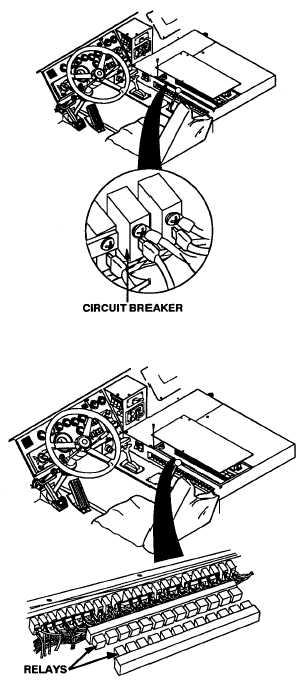
CIRCUIT BREAKER TEST
(1)
Remove eight screws and panel from
console.
(2)
Turn ENGINE switch to ON position.
(3)
Place positive (+) probe of multimeter
on lower terminal of circuit breaker.
(4)
Place negative (-) probe of
multimeter on ground and look for
10-14 volts on multimeter.
(5)
Turn ENGINE switch to OFF position.
WIRES NO. 1031 & NO.
1026 VOLTAGE TEST
(1)
Remove eight screws and
panel from console.
(2)
Turn ENGINE switch to ON
position.
(3)
Place positive (+) probe of
multimeter on wire no. 1031
at HORN relay.
(4)
Place negative (-) probe of
multimeter on ground and look
for 10-14 volts on multimeter.
(5)
Place positive (+) probe of
multimeter on wire no. 1026 at
HORN relay and note reading
on multimeter.
(6)
Turn ENGINE switch to OFF
position.
2-491
|