|
| |
TM 9-2320-360-20-1
WARNING
Ether is very flammable and could explode
causing serious injury or death. Keep
cylinder away from heat and open flame.
Jewelry can catch on equipment and cause
injury or short across electrical circuit and
cause severe bums or electrical shock.
Remove rings, bracelets, watches, necklaces,
and any other jewelry before working around
NET Tractor.
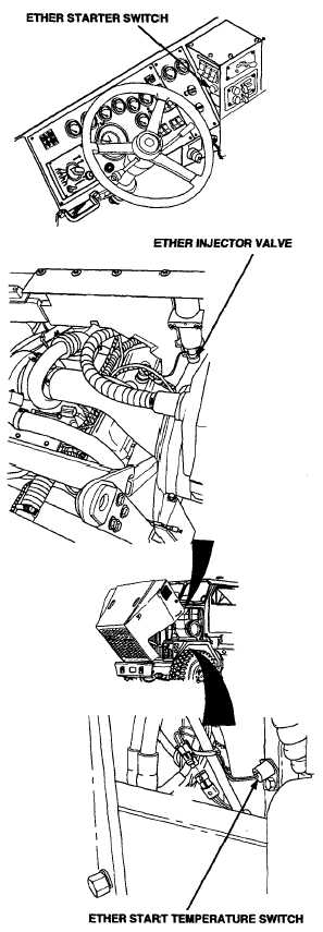
ETHER START switch TEST
(1)
Turn ENGINE switch to ON position.
(2)
Place positive (+) probe of multimeter on
wire no. 1036 at ETHER START switch.
(3)
Place negative (-) probe of multimeter
on ground.
(4)
Press and hold ETHER START switch
and check for 22-28 volts on multimeter.
(5)
Release ETHER START switch.
(6)
Turn ENGINE switch to OFF position.
WIRE NO. 1036 VOLTAGE TEST
(1)
Turn ENGINE switch to ON
position.
(2)
Place positive (+) probe of
multimeter on wire no. 1036 at
ether injector valve.
(3)
Place negative (-) probe of
multimeter on ground.
(4)
Press and hold ETHER START
switch and check for 22-28
volts on multimeter.
(5)
Release
ETHER
START
switch.
(6)
Turn ENGINE switch to OFF
position.
CONTINUITY TEST
CAUTION
Electrical power must be disconnected
from circuit before continuity can be
checked. Failure to comply may result
in damage to test equipment or electrical
system.
(1)
Remove left inner fender (para 16-34).
(1.1) Disconnect wiring from components at each
end of wire.
(2)
Set multimeter to ohms position.
NOTE
A reading of infinity indicates an open
circuit.
(3)
Connect multimeter leads to each end of wire
and check multimeter for continuity.
NOTE
Any reading besides infinity indicates a
grounded wire.
(4)
Remove multimeter lead from one end of wire
and connect to chassis ground.
Change 1 2-487
|