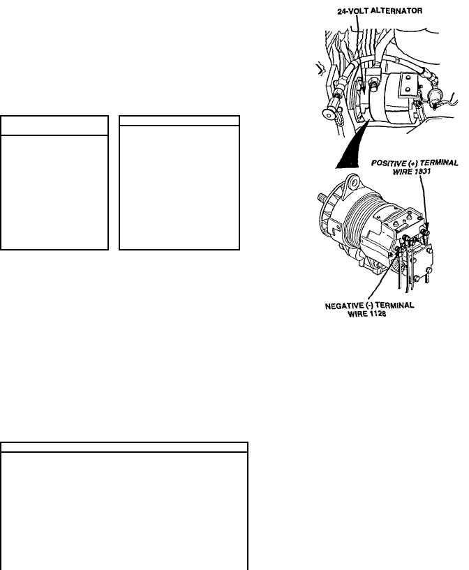
|
| |
TM 9-2320-360-20-1
WARNING
Jewelry can catch on equipment and cause Injury or short
across electrical circuit and cause severe burns or
electrical shock. Remove rings, bracelets, watches,
necklaces, and any other jewelry before working around
HET Tractor.
NOTE
·
STE/ICE-R Test #98 measures voltage to 12-volt
regulator.
·
STE/ICE-R Test #83 measures voltage to 24-volt
regulator.
IGNITION WIRE
STE/ICE TEST #98/83
VOLTAGE TEST
(1)
Connect STEA/CE test
(1)
Turn ENGINE switch
to ON position.
cable
to
STE/ICE
receptacle in cab.
(2)
Place positive (+)
probe of multimeter
(2)
Set STE/ICE test select
switch to '98" or '83".
on IGN terminal of
alternator.
(3)
Start
engine
(TM 9-2320-360-10)
(3)
Place negative (-)
probe of multimeter
on
ground
and
check for over 2
(4)
Press
and
release
TEST button to obtain
test results.
volts on multimeter.
(4)
Turn ENGINE switch
to OFF position.
(5)
Shut
off
engine
(TM 9-2320-360-10).
NOTE
·
The operation of the 12 volt and 24 volt alternators are
related. It is possible for one of the alternators to
influence the gage reading of the other. During
normal operation the BATTERY gages should read 14
volts and 28 volts.
·
A reading of 25 volts and 14 volts indicates that the 24
volt system has failed.
·
If readings appear normal but the batteries on the 12
volt side are low, the 12 volt system is not charging
enough to keep up with the loads applied. The gages
are appearing normal because of the operation of the
24 volt alternator. Refer to para 7-2b to adjust voltage
regulators
NOTE
·
Results of STE/ICE-R Tests #73 and #75 must
both be obtained in order to determine
condition of battery
·
Engine must be capable of cranking to
perform STE/ICE-R Tests #73 and 75.
STE/ICE TEST #73175
(1)
Connect STE/ICE test cable to STEA/ICE receptacle in
cab.
(2)
Set STE/ICE test select switch to 73" or 75".
(3)
Remove DDEC 6-way power harness connector from
ECM.
(4)
Press and hold TEST button until "CAL" appears in
display.
(5)
Release TEST button and wait for offset value to appear
in display.
(6)
Press and release TEST button.
(7)
Attempt to crank engine while observing STE/ICE display
for test results
(8)
Install DDEC 6-way power harness connector on ECM.
Change 2 2-465
|