|
| |
TM 9-2320-360-20-1
WIRE NO. 1284 VOLTAGE TEST
NOTE
ENGINE switch must be
positioned and held to
START to perform this test.
(1)
Turn and hold ENGINE switch to START.
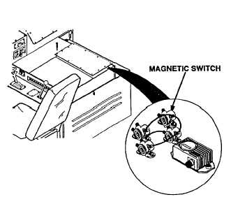
(2)
Place positive (+) probe of multimeter on
wire no. 1284 at starter magnetic switch.
(3)
Place negative (-) probe of multimeter on
ground and look for 22-28 volts on
multimeter.
(4)
Turn ENGINE switch to OFF.
(5)
Inspect wire no. 1284 between magnetic
switches for loose connections and damage
if no voltage is measured.
STARTER MAGNETIC SWITCH
TEST
NOTE
ENGINE switch must be
positioned and held to
START to perform this test.
(1)
Turn and hold ENGINE switch to START.
(2)
Place positive (+) probe of multimeter on
wire no. 1045 at starter magnetic switch.
(3)
Place negative (-) probe of multimeter on
ground and look for 22-28 volts on
multimeter.
(4)
Turn ENGINE switch to OFF.
(5)
Inspect wire no. 1045 between magnetic
switch and starter solenoid for loose
connections and damage if voltage is
measured.
CONTINUITY TEST
CAUTION
Electrical power must be disconnected from
circuit before continuity can be checked.
Failure to comply may result in damage to
test equipment or electrical system.
(1)
Disconnect wire no. 1458 from neutral safety switch and
NEUTRAL relay
Check wire no. 1458 from neutral safety
(2)
Set multimeter to ohms position.
switch to NEUTRAL relay for loose
connections, damage, and continuity.
NOTE
A reading of infinity Indicates an open
circuit.
(3)
Connect multimeter leads to each end of wire no. 1458 and
note reading on multimeter.
NOTE
A reading of other than infinity indicates a
grounded wire.
(4)
Remove multimeter lead from one end of wire and connect
to chassis ground and check multimeter for continuity.
(5)
Connect wire no. 1458 to neutral safety switch and
NEUTRAL relay.
Change 2 2-381
|