Order this information in Print

Order this information on CD-ROM

Download in PDF Format


Click here to make tpub.com your Home Page

Page Title: Turn ENGINE switch ON
Back | Up | Next

Click here for a printed version

Google


Web
www.tpub.com

Home


Information Categories
.... Administration
Advancement
Aerographer
Automotive
Aviation
Combat
Construction
Diving
Draftsman
Engineering
Electronics
Food and Cooking
Math
Medical
Music
Nuclear Fundamentals
Photography
Religion
USMC
   
Products
  Educational CD-ROM's
Printed Manuals
Downloadable Books


TM 9-2320-360-20-1 NOTE The  following  flow  chart  should  only  be used if DDEC troubleshooting was started on p. 2-82 and you were referred here. (1)     When following appropriate Historic Codes, check for: a.) Poor  mating  of  connector  halves  or terminals    not    fully    seated    in    the connector body. b.) Improperly formed or damaged terminals.    All  connectors  in  problem circuit should be checked. (2)    Carefully  inspect  all  wiring  in  the  affected circuit. (3)    Do not replace any components unless you have  followed  the  procedure  to  completion and have found no faults. 
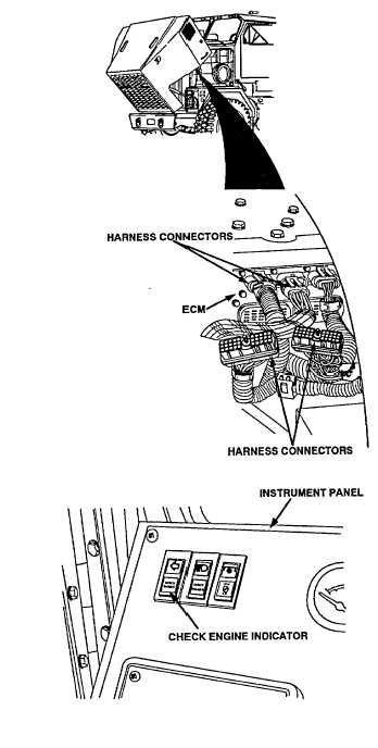
(4)    After  repairs  have  been  made,  clear  codes (mode 40) and proceed to question (3). Turn ENGINE switch ON and observe CHECK ENGINE indicator. Change 1  2-327

Privacy Statement - Press Release - Copyright Information. - Contact Us - Support Integrated Publishing

Integrated Publishing, Inc. - A (SDVOSB) Service Disabled Veteran Owned Small Business