|
| |
TM 9-2320-360-20-1
CAUTION
Use jumper wire only between terminals
indicated Failure to comply may result in
damage to DDEC components or wiring.
NOTE
The following flow chart should only be
used
if
DDEC
troubleshooting
was
started on p. 2-80 and you were referred
here.
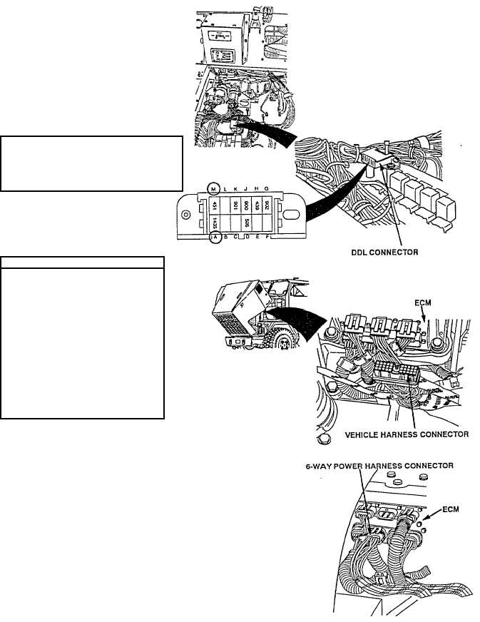
(1)
First unplug DDR.
(2)
Short pin A to pin M on 12-pin DDL
connector and read codes flashing
out on the CHECK ENGINE light.
CONTINUITY TEST
(3)
Turn ENGINE switch OFF.
(4)
Disconnect both vehicle
harness and 6-way power
connector.
(5)
Install jumper wire between E1
of vehicle harness connector
and socket D of 6-way power
harness connector.
(6)
Read resistance between
sockets A and M on 12- pin,
DDL connector.
Check terminals at both vehicle harness
and 6-way power harness connectors
(both the ECM and harness side) for
damage; bent, corroded and unseated
pins or sockets.
2-315
|