|
| |
TM 9-2320-360-20-1
1-19. CENTRAL TIRE INFLATION SYSTEM (CTIS)
The Central Tire Inflation System (CTIS) allows the HET operator to adjust the vehicle tire pressure to one of four
predetermined settings. Each tire pressure setting has a vehicle speed limitation. If the average vehicle speed exceeds
this limit, the CTIS will activate an overspeed light.
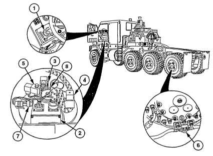
The CTIS consists of five major components. An electronic controller (1), mounted on the dash, contains the switches
and indicator lights for system operation. The controller's Read Only Memory (ROM) contains the working instructions for
the power manifold (2).
The power manifold (2), located under the driver's seat, contains an inflation valve (3) for increasing tire pressures and a
deflation valve (4) to reduce tire pressures. The power manifold's quick-release valve (5) is closed during checking,
inflating, and deflating modes. The quick-release valve opens at the end of a cycle to rapidly exhaust all air pressure from
the CTIS, which in turn closes all wheel valves (6).
The power manifold (2) has two other components in addition to the valves. They are a pressure transducer (7) that
monitors system pressure for the CTI controller and a low air pressure switch (8) used to shut the CTIS off when chassis
air pressure is less than 85 psi. 110 psi is required to restart the system.
Directly under the power manifold (2) is the porting block, to which the air lines to the axles are connected. Air pressure
passes through these lines and the axle assemblies to the wheel valves (6). Air pressure is present in the CTIS lines only
when the system is monitoring (or adjusting) tire pressures. At all other times, the system has no air pressure.
The CTIS has an automatic routine that checks for moderate to large air leaks or air loss. During the initial start of the
CTIS, the quick-release valve (5) is closed and the inflation valve (3) opens to attempt to build system pressure. If the
transducer fails to sense that the system is capable of maintaining pressure, the CTIS will shut itself off and display a
flashing low air light.
When the CTIS has completed a pressure adjustment cycle, the controller (1) starts an internal timer. If no changes occur
during the next 15 minutes, a check cycle is automatically activated, during which tire pressures are measured and
adjusted if necessary. This provides for improved tire life as hot tire pressures are adjusted and slowly leaking tires are
kept inflated.
1-11 (1-12 blank)
|