|
| |
TM 9-2320-360-20-1
NOTE
The following flow chart should only
be used if DDEC troubleshooting
was started on p. 2-80 and you
were referred here.
VOLTAGE TEST
(1)
Turn ENGINE switch OFF.
(1.1) Remove right inner fender
(para 16-34).
(2)
Disconnect oil pressure
sensor (OPS) and turbo
boost sensor (TBS)
connectors.
(3)
Turn ENGINE switch ON.
(4)
At each sensor harness
connector, read voltage
between socket C (red
lead) and socket A (black
lead).
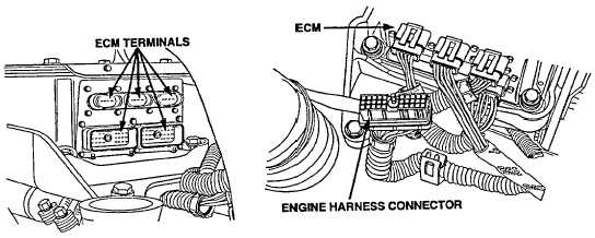
Check terminals at ECM engine harness
connector (both ECM and harness side)
for damage; bent, corroded, and
unseated pins or sockets.
Change 1 2-275
|


