|
| |
TM 9-2320-360-20-1
NOTE
The following flow chart should only be
used if DDEC troubleshooting was
started on p. 2-80 and you were
referred here.
VOLTAGE TEST
(1)
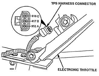
Turn ENGINE switch OFF and
disconnect the Throttle Position Sensor
(TPS).
(2)
Turn ENGINE switch ON and read
voltage on the TPS harness connector,
pin C (red lead) to pin A (black lead).
CAUTION
Use jumper wire only between
terminals indicated. Failure to
comply may result in damage to
DDEC components or wiring.
CONTINUITY TEST
(1)
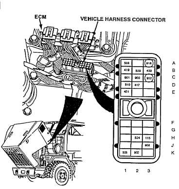
Turn ENGINE switch OFF and
disconnect vehicle harness connector at
ECM.
(2)
Install a jumper wire between pins A and
C of TPS harness connector.
(3)
Read resistance between sockets A3 and
C3 of vehicle harness connector.
2-267
|