|
| |
TM 9-2320-360-20-1
1-17. AIR SYSTEM
The air system operates the service and parking brakes, rear suspension system, and the CTIS. The air system also
enables operation of the transfer case and interaxle lockups, winch tensioners and kickouts, windshield washer, and
horns.
The air system on the HET Tractor consists of an engine-driven air compressor (1), a purge tank (2), and five air
reservoirs (3 thru 7). Reservoir (3) supplies air to reservoirs (4 thru 7). Three reservoirs (5 thru 7) are interconnected and
separated from reservoir (4) with check valves. Air from reservoir (4) is supplied to service brakes on all four axles and
parking brakes on the rear tridem axles, transfer case and interaxle lockups, winch tensioners and kickouts, windshield
washer, and horns. The service brakes are actuated by relay valves which are controlled by the operator pressing the
brake treadle in the cab. The parking brakes are also actuated by relay valves which are controlled by hand controls. In
the event of the loss of system air pressure, the spring brake valve will modulate the parking brakes so the HET Tractor
can be stopped safely. Reservoirs (5 thru 7) supply air to operate the CTIS, service and parking brakes on rear tridem
axles, and rear suspension system. Air is drawn from the engine air intake and routed to the air compressor (1) where it
is pressurized. Air dryers (8 and 9) remove moisture from the pressurized air. Air from the dryers goes to the purge
reservoir (2) and air reservoir (3).
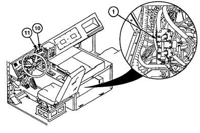
System protection elements include an air cleaner restriction indicator (10) that determines whether air flow through the
air cleaner is impeded. In the cab, air pressure in reservoir (4) is indicated by the green needle on the AIR PRESSURE
gage (11). The red needle on the gage (11) indicates air pressure in reservoirs (5 thru 7). If air pressure falls below 60
psi (414 kPa) in any of the reservoirs, warning alarm will sound and LOW AIR indicator will light.
The rear suspension system contains a pair of suspension air springs on each rear axle that automatically inflates or
deflates according to load. Air to the air springs is regulated by a height control valve.
Purging the air in the air dryers is automatically done when 125 psi (862 kPa) system pressure is reached at the
compressor. The compressor cycle is stopped and air from purge tank clears accumulated water through a valve on the
bottom of the air dryer.
Air to the transfer case enables engagement of four-wheel drive in high or low gear range. An interaxle lockup pilot valve
also prevents the axles from locking up in high ranges.
1-8 Change 1
|