|
| |
TM 9-2320-360-20-1
CAUTION
Use jumper wire only between terminals
indicated. Failure to comply may result in
damage to DDEC components or wiring.
NOTE
·
The following chart should be used only
if DDEC troubleshooting was started on
pg. 2-80 and you were referred here.
·
A false DDEC historical Code 14 may be
logged during cold starts in extremely
cold environments, -50 to -26F° (-46 to -
32° C). Typically, the CHECK ENGINE
light will come on 8 minutes after starting
and go out 2-3 minutes later. If the
vehicle has been operated under these
conditions, clear the historical codes and
return the vehicle to service.
(1)
Turn ENGINE switch OFF.
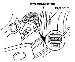
(2)
Disconnect OTS and install a jumper between OTS
connector sockets A and B.
(2.1) Click on 'Alarms Clear" to clear alarms screen.
(3)
Turn ENGINE switch ON and read active codes.
WARNING
·
Batteries must be disconnected before
tightening any connections. Failure to
comply may result in injury to personnel.
·
Remove all jewelry such as rings, dog
tags, bracelets, etc. If jewelry contacts
electrical terminals a direct short may
result in an instant heating of tools,
damage to equipment, and injury to
personnel.
CONTINUITY TEST
(1)
Turn ENGINE switch OFF and remove jumper.
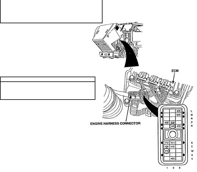
(2)
Disconnect engine harness connector at ECM.
(3)
Read resistance between sockets R2 and W1
on engine harness connector.
Inspect OTS and terminals at OTS connectors (both sensor
and harness sides) for damage; bent, corroded, and
unseated pins or sockets
Change 2 2-127
|