|
| |
TM 9-2320-360-20-1
NOTE
The following flow chart should
only
be
used
if
DDEC
troubleshooting was started on
p. 2-80 and you were referred here.
(1)
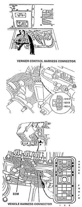
Turn ENGINE switch OFF and unplug
vernier control sensor connector.
(1.1) Click on "Alarms Clear" to clear
alarms screen.
(2)
Turn ENGINE switch ON and read
active codes.
CAUTION
Use
jumper
wire
only
between
terminals Indicated. Failure to comply
may result in damage to DDEC
components or wiring.
CONTINUITY TEST
(1)
With transmission in neutral, turn ENGINE
switch OFF.
(2)
Install a jumper wire between pin A and pin
B of vernier control harness connector.
(3)
Disconnect vehicle harness connector at
ECM.
(3.1) Turn engine switch ON.
(3.2) Push ENGINE SPEED CONTROL switch
to ENGINE HIGH IDLE position
(TM 9-2320-360-1 0).
(3.3) Push and release ENGINE SPEED
CONTROL switch forward to engage
DDEC HI IDLE relay (TM 9-2320-360-10)
(4)
Read resistance between sockets C3 and
D1 on the vehicle harness connector.
(5)
Turn engine switch OFF.
Change 3 2-117
|