|
| |
TM 9-2320-360-20-1
WARNING
Jewelry can catch on equipment and cause
injury or short across electrical circuit and
cause severe burns or electrical shock.
Remove rings, bracelets, watches, necklaces,
and any other jewelry before working around
HET Tractor.
NOTE
The following flow chart should be used if
DDEC troubleshooting was started on p. 2-80
and you were referred here.
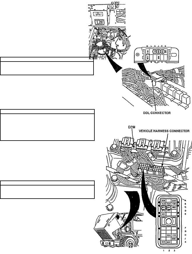
VOLTAGE TEST
(1)
Turn ENGINE switch ON.
(2)
Read voltage at 12-pin DDL connector from pin
H (red lead) to pin A (black lead).
CAUTION
Use jumper wire only between terminals
indicated. Failure to comply may result In
damage to DDEC components or wiring.
RESISTANCE TEST
(1)
Turn ENGINE switch OFF and remove jumpers
from 12-pin DDL connector.
(2)
Place jumper across pins J and K on 12-pin
connector.
(3)
Unplug vehicle harness connector and measure
resistance between sockets C1 and C2.
RESISTANCE TEST
(1)
Remove jumpers from 12-pin DDL connector.
(2)
Read resistance between sockets C1 and C2 of
vehicle harness connector.
2-103
|