|
| |
TM 9-2320-356-BD
Section III. TEST EQUIPMENT
B-3.
FIELD EXPEDIENT TEST EQUIPMENT
General Information:
Sometimes,
in the process of assessing the battlefield damage, it is necessary to
make voltage and resistance measurements to determine where the fault is.
Standard
test equipment (voltmeter, ohmmeter, SWR meter, etc.) should be used whenever
possible.
If standard test equipment is not available, field expedient equipment
can be fabricated using parts commonly found on the vehicle and in the forward
maintenance areas.
The following paragraph provides fabrication instructions for
making a voltmeter, ohmmeter,
and RF transmitter output test.
NOTE
Accurate measurements are not available. These
are Go-No-Go meters.
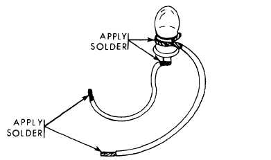
1.
Making a Voltmeter.
A voltmeter can be made from a light
bulb and two pieces of wire. The
pieces of wire can be connected to the
case and center terminal of the bulb
by means of solder, twisting, or
simply holding the wire ends against
the bulb (see illustration). The
voltage rating of the bulb should be
close to the value of the expected
voltage being measured.
For voltages
in the 18 to 30 vdc range, any light
bulb on the driver’s master panel,
driver’s instrument panel, gunner’s
panel, commander’s panel, or gunner’s
primary sight can be used. For
voltages of 5 vdc or less a
two-battery cell flashlight bulb can
be used.
The presence of voltage will
cause the bulb to glow.
Polarity of
dc voltage does not have to be
observed; even ac voltage can be
measured.
Twist exposed wire ends
together and apply solder, if
available, and solder.
Touch to
voltage source when ready to make
measurement.
B-6
|