|
| |
TM 9-2320-356-BD
CHAPTER 14
WRECKER AND CRANE ASSEMBLIES
BDAR FIXES SHALL BE USED ONLY IN COMBAT
AT THE DISCRETION OF THE COMMANDER
AND SHALL BE REPAIRED BY STANDARD MAINTENANCE PROCEDURES
AS SOON AS PRACTICABLE AFTER THE MISSION IS COMPLETED.
Section I. GENERAL
14-1.
GENERAL
The wrecker crane consists of the wrecker unit that is mounted above the truck
chassis, with the exception of the rear-mounted winch.
The various functions of
the wrecker crane are dependent on all of the hydraulic and mechanical units built
into the crane.
The power for the wrecker crane is supplied by the truck engine
through a bevel gearbox hydraulic pump.
This pump forces fluid to each of the
hydraulically actuated units.
The control of the various functions is in the
control valve bank.
From there the fluid is directed under high pressure to
operate any of the following:
the elevating cylinders for raising or lowering the
boom, the boom crowd cylinder for extending or retracting the boom, the swing motor
for revolving the crane,
and the hoist motor for winding and unwinding the hoist
cable.
A special cone-type worm and drive gear transmits the power for turning the
hoist drum and revolving the crane.
The following procedures deal with the M543,
M816, and M936 5-ton wrecker components.
14-2.
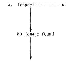
ASSESSMENT CHART
NOTE
The engine must be operational to assess the
hydraulic system.
Damage found to:
-Hydraulic pump
and bevel gearbox; . . go to paragraph 14-5
-Swing hydraulic
motor and gearbox; . . go to paragraph 14-6
-Boom elevating and
crowd cylinders; . . . . go to paragraph 14-7
-Control valve
bank assembly;
. . . . .
go to paragraph 14-8
-Boom hoist hydrau-
lic motor and drum
assembly;
. . . . . . . . . . . go to paragraph 14-9
-Hydraulic reser-
voir; . . . . . . . . . . . . . . . go to paragraph 14-10
-Hydraulic filter; . . . go to paragraph 14-11
-Wire rope or cable; . go to paragraph 14-12
14-1
|

