 |
|||
|
|
|||
|
Page Title:
Illustration 216 Schematic Drawing |
|
||
| ||||||||||
|
|
 86
TM 9-2320-312-24-2
Truck Engine
Disassembly and Assembly Section
5. Replace rod bearing (6) by pressing a new
bearing into the connecting rod. Refer to Special
NOTICE
Instruction, SEHS7295 for the correct tooling and
Verify correct assembly of the pistons and the con-
the correct installation procedure.
necting rods. Ensure that the etched numbers on the
rod and the rod cap are in the correct positions. The
etched number on the rod and the rod cap correspond
to the cylinder in which it should be installed.
g00610503
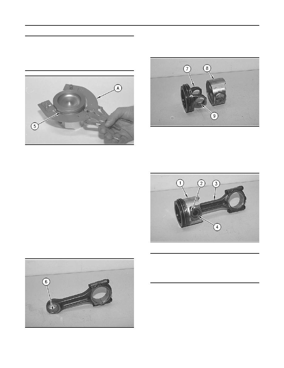
Illustration 218
6. The piston is a two-piece assembly. This piston
consists of piston crown (7) and piston skirt (8).
g00610428
Illustration 216
Inspect bearing (9) in the piston crown (7). The
piston crown must be replaced if the piston
1. Check the clearance between the ends of piston
crown is worn or damaged. Bearing (9) is not
rings (5). Refer to the Specifications Manual,
serviced.
"Pistons and Rings" topic.
Note: The oil ring must be installed over the spring
with the end gap 180 degrees from the oil ring
spring joint.
2. Install the oil control piston ring with Tool (A).
The ends of the spring should be rotated 180
degrees from the ring end gap.
3. Install the intermediate piston ring with the side
marked "UP-2" toward the top of the piston. Use
Tool (A) in order to install the ring.
4. Install the top piston ring with the side marked
g00610426
"UP-1" toward the top of the piston. Use Tool (A)
Illustration 219
in order to install the ring.
NOTICE
An improperly installed retainer ring could cause the
piston and connecting rod to come apart during en-
gine operation. This action can result in a broken Pis-
ton Skirt and major engine damage.
7. Position piston (1) on connecting rod (3). Coat
pin (4) with clean engine oil and install pin (4).
Ensure that the retainer rings are in the grooves
of piston (1).
End By:
g00610498
Refer to Disassembly and Assembly, "Piston and
Illustration 217
Connecting Rods - Install".
|
|
Privacy Statement - Press Release - Copyright Information. - Contact Us |
